CMOS imaging chips have been steadily improving, their cost and performance being driven by the highly competitive smartphone industry. As CMOS sensors get better and cheaper, they get more interesting for hacker lab projects. In this post I’m going to demonstrate a few applications of the high-resolution sensor that you’ve already got in your pocket — or wherever you store your cell phone.
CMOS vs CCD
First lets quickly review image sensors. You’ve probably head of CMOS and CCD sensors, but what’s the difference exactly?
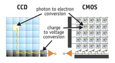
CCD and CMOS imaging sensors: from this excellent page at CERN.
As the figure above shows, CCD and CMOS sensors are both basically photodiode arrays. Photons that hit regions on the chip are converted into a charge by a photodiode. The difference is in how this charge in shoved around. CCD sensors are analogue devices, the charge is shifted through the chip and out to a single amplifier. CMOS sensors have amplifiers embedded in each cell and also generally include on-chip analogue to digital conversion allowing complete “camera-on-a-chip” solutions.
Because CMOS sensors amplify and move the signal into the digital domain sooner, they can use cheaper manufacturing processes allowing lower-cost imaging chips to be developed. Traditionally they’ve also had a number of disadvantages however, because more circuitry is included in each cell, less space is left to collect light. And because multiple amplifiers are used, it’s harder to get consistent images due to slight fabrication differences between the amplifiers in each cell. Until recently CMOS sensors were considered a low-end option. While CCD sensors (and usually large cooled CCD sensors) are still often preferred for scientific applications with big budgets, CMOS sensors have now however gained in-roads in high performance DSLRs.
Our bodies rely on DNA to function, it’s often described as “the secret of life”. A computer program that describes how to make a man. However inaccurate these analogies might be, DNA is fundamental to life. In order for organisms to grown and replicate they therefore need to copy their DNA.
Since the discovery of its structure in 1953, the approximate method used to copy DNA has been obvious. The information in DNA is encoded in 4 nucleotides (which in their short form we call A,T,G, and C). These couple with each other in pairs, forming 2 complimentary strands that mirror each other. This structure naturally lends itself to replication. The two strands can dissociate (under heat we call this melting), and new strands form around each single stranded template.
However, this replication process can’t happen all by itself, it requires assistance. And it wasn’t until we discovered an enzyme called the DNA polymerase that we understood how this worked. In conjunction with other enzymes, double stranded DNA is unwound into 2 single strands which are replicated by the polymerase.
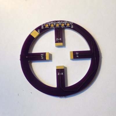
Recently I’ve been getting curious about interesting PCB shapes. In the past I’ve always used simple Polygons, perhaps rounding out the corners to make the design a little more aesthetically pleasing. The board to the right was my introduction to the possibilities of oddly shaped boards. It’s designed to couple with a piezo buzzer (used as an actuator). I’ve been planning to have it fabricated out of FPC (Flexible Printed Circuits), but with fabrication being so cheap I sent it to OSHPark to see what they’d make of it. OSHPark doesn’t have hard specs around internal routing, but in my experience they’re up to try anything (and they’re quality is always great). The width of the prongs on the PCB shown is 5mm. I figured it was a risk, and that it was likely the FR4 could break, but it came back great!
This has led me to the realization that my boards could look much more exciting than they do currently, and that our highly optimized modern PCB fabrication process provides a lot of room for experimentation. This article will discuss some of the options available when creating non-traditional PCBs.
This week I was approached with a question. Why don’t passenger aircraft have emergency parachutes? Whole plane emergency parachutes are available for light aircraft, and have been used to great effect in many light aircraft engine failures and accidents.
But the truth is that while parachutes may be effective for light aircraft, they don’t scale. There are a series of great answers on Quora which run the numbers of the size a parachute would need to be for a full size passenger jet. I recommend reading the full thread, but suffice it to say a ballpark estimate would require a million square feet (92903 square meters) of material. This clearly isn’t very feasible, and the added weight and complexity would no doubt bring its own risks.
Recently I’ve been learning more about classic analog music synthesizers and sequencers. This has led me to the Baby10, a classic and simple analog sequencer design. In this article I’ll introduce its basic operation, and the builds of some awesome hackers based on this design.
Sequencers produce, a sequence of varying voltages. These control voltages (CV) can then be use to control other components. Often this is a simple tone generator. While the concept is simple, it can produce awesome results:
A basic sequencer is a great beginners project. It’s easy to understand the basic operation of the circuit and produces a satisfyingly entertaining result. The Baby 10 was originally published in a column called “Captain’s Analog”, but has now been widely shared online.
The original Baby10 article.
The circuit uses the 4017, a simple CMOS decade counter. The 4017 takes an input clock signal then sequentially outputs a high pulse on each of 10 output pins. As such, the 4017 does almost everything we need from a sequencer in a single IC! However, we want our sequencer to output a varying voltage which we can then use to generate differing tones.
To accomplish this variable resistors are connected to each of the output pins. A diode in series with the variable resistor stops the outputs fighting against each other (in layman’s terms).
To make the sequencer more visually attractive (and give some feedback) LEDs are often also added to the output of the 4017. A complete Baby 10 sequencer is shown in the schematic below. The original circuit used 1N917s, these are no longer available but the part has been replaced by the 1N4148.
No doubt many of you have spent a happy Christmas tearing away layers of wrapping paper to expose some new gadget. But did you stop to spare a thought for the “sticky-back plastic” holding your precious gift paper together?
There are a crazy number of adhesive tapes available, and in this article I’d like to discuss a few of the ones I’ve found useful in my lab, and their sometimes surprising applications. I’d be interested in your own favorite tapes and adhesives too, so please comment below!
But first, I’d like to start with the tapes that I don’t use. Normal cellulose tape, while useful outside the lab, is less than ideally suited to most lab applications. The same goes for vinyl-based insulating tapes, which I find have a tendency to fall off leaving a messy sticky residue. When insulation is necessary, heatshrink seems to serve better.
The one tape I have in my lab which is similar to common cellulose tape however is Scotch Magic Tape. Scotch Magic tape, made from a cellulose acetate, and has a number of surprising properties. It’s often favored because of it’s matte finish. It can easily be written on and when taped to paper appears completely transparent. It’s also easy to tear/shape and remove. But for my purposes I’m more interested in it’s scientific applications.
Here’s a neat trick you can try at home. Take a roll of tape (I’ve tried this with Scotch Magic tape but other tapes may work too) to a dark room. Now start unrolling the tape and look at interface where the tape leaves the rest of the roll. You should see a dim blue illumination. The effect is quite striking and rather surprising. It’s called triboluminescence and has been observed since the 1950s in tapes and far earlier in other materials (even sugar when scraped in a dark room will apparently illuminate). The mechanism, however, is poorly understood.
It was perhaps this strange effect that led researchers to try unrolling tape in a vacuum. In 1953 a group of Russian researchers attempted this and bizarrely enough, were able to generate X-rays. Their results were unfortunately forgotten for many years, but were replicated in 2008 and even used to X-ray a researcher’s finger! As usual Ben Krasnow has an awesome video on the topic:
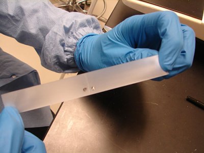
In my lab however I mostly use Scotch tape to remove surface layers. In certain experiments it’s valuable to have an atomically flat surface. Both Mica and HOPG (a kind of graphite) are composed of atomically flat layers. Scotch tape can be used to remove the upper layers leaving a clean flat surface for experimentation.
Researchers have also modified this technique to produce graphene. Graphene is composed of single carbon layers and has a number of amazing properties, highly conductive, incredibly strong, and transparent. For years producing small quantities of graphene provided difficult. But in 2004 a simple method was developed at the University of Manchester using nothing but bulk ordered graphite (HOPG) and a little Scotch tape. When repeatedly pressed between the Scotch tape, the Graphite layers can be separated until eventually only a signal layer of graphene remains.
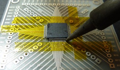
The other non-conductive tape I use regularly in my lab is of course Kapton tape. While Kapton is a Dupoint brand name, it’s basically a polyimide film tape which is thermally stable up to 400 degrees C. This makes it ideal for work holding in electronics (or masking out pins) when soldering. You can also use it for insulating (though it’s inadvisable for production applications). Typically polyimide tape is available under a number of dubious synonyms (one example is Kaptan) from a variety of Chinese suppliers at low cost.
Carbon tape is conductive in all axes. This means it you can create a electrical connection by simply taping to your devices. It’s resistance however is somewhat high. I’ve most commonly come across this when using electron microscopes. Carbon tape is used both to keep a sample in place and create an electrical connection between the sample and the sample mount.
Carbon tape, applied to a SEM mount.
Other conducting tapes are available with lower resistance, creating a electrical connection without soldering is valuable in a number of situations. Particularly when heat might damage the device. One example of this is piezoelectric materials. Not only does solder often bond poorly to ceramic materials, but it may also depole the material removing its piezoelectric properties. I tend to use conductive epoxies in these situations, but conductive tapes appear to be an attractive option.
Aluminum tape is commonly used for (heat) insulation in homes. It’s therefore very cheap and easily available. As well as conducting heat aluminum tape of course also conducts electricity. Around the lab this can be pretty handy. While the adhesive is not conductive, making it less attractive for connection parts, I’ve found aluminum tape great of sealing up holes in shielded enclosures. It also makes a great accompaniment to aluminum foil which is used to provide ad-hoc shielding in many scientific environments. Copper tape is also easily obtained, though slightly more expensive.
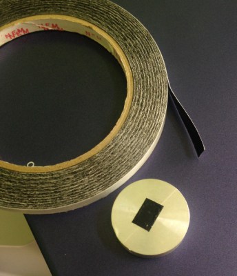
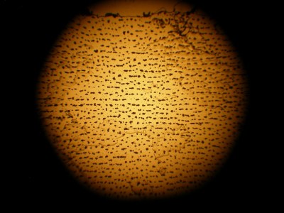
Z tape under a microscope
A much less common, but far cooler conductive tape is so called Z tape. This tape is composed of regular double-sided tape impregnated with spaced conductors. The result is a tape that conducts in only one direction (from the top to the bottom). This makes it similar in structure to a zebra strip, commonly used to connect LCDs. Z tape is unfortunately pretty expensive, a short 100mm strip can cost 5 dollars. What exactly 3M had in mind when creating Z tape is unclear. But it can be used for repairing FPC connectors on LCDs or in other situations where soldering is impractical.
One of the more awesome applications is Jie and Bunnie’s circuit sticker project. The kits are designed to allow kids to assemble circuits simply by sticking components together. Z tape is ideal for this, as it allows multiple connections to be made using the same piece to tape.
I couldn’t write an article on tape without mentioning the somewhat apocryphal “Invisible Electrostatic Wall” incident. A report at the 17th Annual EOS/ESD Symposium describes a “force field” like wall that appeared during the production of polypropylene film. While the story seems slightly dubious, it reminds us of the surprising applications and utility of tapes.
Next time you’re sending off a package or ripping open a package, spare a thought for the humble tape that holds it together.
Motors are everywhere; DC motors, AC motors, steppers, and a host of others. In this article, I’m going to look beyond these common devices and search out more esoteric and unusual electronic actuators that might just find a place in one of your projects. In any case, their mechanisms are interesting in their own right! Join me after the break for a survey of piezo, magnetostrictive, magnetorheological, voice coils, galvonometers, and other devices. I’d love to hear about your favorite actuators and motors too, so please comment below!
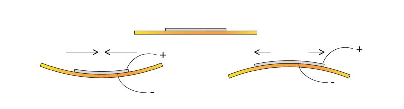
Piezoelectric materials sometimes seem magic. Apply a voltage to a piezoelectric material and it will move, as simple as that. The catch of course is that it doesn’t move very much. The piezoelectric device you’re probably most familiar with is the humble buzzer. You’d usually drive these with less than 10 volts. While a buzzer will produce a clearly audible sound you can’t really see it flexing (as it does shown above).
To gauge the motion of a buzzer I recently attempted to drive one with a 150 volt piezo driver, this resulted in a total deflection of around 0.1mm. Not very much by normal standards!
The PiezoMotor LEGS actuator “walks” along a rod, pushing it as it goes.
For some applications however resolution is of primary interest rather than range of travel. It is here that piezo actuators really shine. The poster-boy application of piezo actuators is perhaps the scanning probe microscope. These often require sub-nanometer accuracy (less than 1000th of 1000th of 1 millimeter) in order to visualize individual atoms. Piezo stacks are ideal here (though hackers have also used cheap buzzers!).
Sometimes though you need high precision over a larger range of travel. There are a number of piezo configurations that allow this. Notably Inchworm, “LEGS”, and slip-stick actuators.
The PiezoMotor LEGS actuator is shown to the above. As noted, Piezos only produce small (generally sub-millimeter) motion. Rather than using this motion directly, LEGS uses this motion to “walk” along a rod, pushing it back and forth. The rod is therefore moved, in tiny nanometer steps. However, piezos can move quickly (flexing thousands of times a second). And the LEGS (and similar Inchworm actuator) allows relatively quick, high force, and high resolution motion.
The tablecloth trick (yes this one’s fake, the kid is ok don’t worry. :))
Another type of long travel piezo actuator uses the “stick-slip phenomenon”. This is much like the tablecloth magic trick shown above. If you pull the cloth slowly there will be significant friction between the cloth and this crockery and they will be dragged along with the cloth. Pull it quickly and there will be less friction and the crockery will remain in place.
This difference between static and dynamic friction is exploited in stick-slip actuators. The basic mechanism is shown in the figure below.
Motion caused by a stick-slip motor
When extending slowing a jaw rotates a screw, but if the piezo stack is compressed quickly the screw will not return. The screw can therefore be made to rotate. By inverting the process (extending quickly, then compressing slowly) the process is reversed and the screw is turned in the opposite direction. The neat thing about this configuration is that it retains much of the piezo’s original precision. Picomotors have resolutions of around 30 nanometer over a huge range of travel, typically 25mm, they’re typically used for optical focusing and alignment and can be picked up on eBay for 100 dollars or so. Oh and they can also be used to make music. Favorites include Stairway to Heaven, and not 1 but 2 versions of Still Alive (from Portal). Obligatory Imperial March demonstration is embedded here:
There are numerous other piezo configurations, but typically they are used to provide high force, high precision motion. I document a few more over on my blog.
Magnetostrictive actuators
Magnetostriction is the tendency of a material to change shape under a magnetic field. We’ve been talking about magnetostriction quite a lot lately. However much like piezos it can also be used for high precision motion. Unlike piezos they require relatively low voltages for operation and have found niche applications.
Magnetorheological motion
Magnetorheological (MR) fluids are pretty awesome! Much like ferrofluids, MR fluids respond to changes in magnetic field strength. However, unlike ferrofluids it’s their viscosity that changes.
This novel characteristic has found applications in a number of areas. In particularly the finishing of precise mirrors and lens used in semiconductor and astronomical applications. This method uses an electromagnet to change the viscosity of the slurry used to polish mirrors, removing imperfections. The Hubble telescope’s highly accurate mirrors were apparently finished using this technique (though hopefully not that mirror). You can purchase MR fluid in small quantities for a few hundred dollars.
Electrostatic motors
While magnetic motors operate through the attraction and repulsion of magnetic fields, electrostatic motors exploit the attraction and repulsion of electric change to produce motion. Electrostatic forces are orders or magnitude smaller that magnetic ones. However they do have niche applications. One such application is MEMS motors, tiny (often less than 0.01mm) sized nanofabricated motors. At these scales electromagnetic coils would be too large and specific power (power per unit volume) is more important than the magnitude of the overall force.
Voice coils and Galvanometers
The voice coil is your basic electromagnet. They’re commonly used in speakers, where an electromagnet in the cone reacts against a fixed magnet to produce motion. However voice coil like configurations are used for precise motion control elsewhere (for example to focus the lens of an optical drive, or position the read head of a hard disc drive). One of the cooler applications however is the mirror galvanometer. As the name implies the device was originally used to measure small currents. A current through a coil moved a rod to which a mirror was attached. A beam of light reflect off the mirror and on to a wall effectively created a very long pointer, amplifying the signal.
These days ammeters are far more sensitive of course, but the mirror galvanometer has found more entertaining applications:
High speed laser “galvos” are used to position a laser beam producing awesome light shows. Modern systems can position a laser beam at kilohertz speeds, rendering startling images. These systems are effectively high speed vector graphic like line drawing systems, resulting in a number of interesting algorithmic challenges. Marcan’s OpenLase framework provides a host of tools for solving these challenges effectively, and is well worth checking out.
In this article I’ve tried to highlight some interesting and lesser known techniques for creating motion in electronic systems. Most of these have niche scientific, industrial or artistic applications. But I hope they also also offer inspiration as you work on your own hacks! If you have a favorite, lesser known actuator or motor please comment below!


 This novel characteristic has found applications in a number of areas. In particularly the finishing of precise mirrors and lens used in semiconductor and astronomical applications. This method uses an electromagnet to change the viscosity of the slurry used to polish mirrors, removing imperfections. The Hubble telescope’s highly accurate mirrors were apparently finished using this technique (though hopefully not


