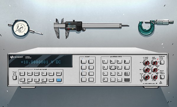
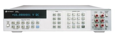
Among multimeters one instrument stands far and above the rest. An object desired for its accuracy, resolution and shear engineering beauty. I speak of course of the HP 3458A. That’s right, not Keysight, not even Agilent (though of course it goes by those brands too). The 3458A was released in 1989, when HP was still… well… HP. An elegant meter from a more civilized age. As the HP Journal documents, the 3458A was a significant engineering feat and has remained in production (and largely unchallenged) for the last 26 years.
But what, you might ask, makes the 3458A such a significant and desirable instrument? It’s all in the digits. The 3458A is one of the few 8.5 digit multimeters available. It is therefore sensitive to microvolt deflections on 10 volt measurements. It is this ability to distinguished tiny changes on large signals that sets high precision multimeters apart. Imagine weighing an elephant and being able to count the number of flies that land on its back by the change in weight. The 3458A accomplishes a similar feat.
Gavin Morris has been working on his awesome sound responsive LED sculptures for a while. Technically the sculpture is an interesting application of WS2812 RGB LEDs, Raspberry Pis and a load of styrofoam cups and flower pots. However the artistic development, and inspiration for this project is equally interesting. Gavin shares his thoughts and a brief technical description of the project below.
Akihabara, Tokyo has transformed over the years. In its present form Akihabara emerged from the ruins of a devastated Tokyo after World War 2 when the entire district was burnt to the ground. The area was rebuilt in the shadow of the Akiba Jinja (dedicated to the god of fire prevention), and a new breed of street vendors began to appear. Huddling under the protection of railway bridges, and dealing mostly in Black market radio parts, these vendors set a new tone to what would become Japan’s “Electric Town”. And as Japanese manufacturing prowess grew so too did Akihabara.
Maids touting for business
Now of course Akihabara is also home to Otaku culture, and is perhaps best known in this regard for its maid cafes. Streets are littered with maids touting their cafes, somewhat incongruously among computer outlets and precision tooling stores.
My interests however lie squarely in Akihabara’s glorious junk bins. Of all places I think I’m happiest digging through this mass of discarded technology from Japan’s manufacturing past.
A tour through the junks bins is like an archaeological dig. And in this article I will present some recent finds, and ponder on their relevance to Japanese manufacturing.
[Akiba] over at FreakLabs just put up a detailed tutorial outlining how to control and sequence lighting wirelessly using an Arduino and Vixen lighting sequencer software.
For those that don’t know [Akiba], he’s the guy behind Wrecking Crew Orchestra (TRON Dance) and their EL wire costumes. [Akiba] hacks on his projects at Hacker farm out in rural Japan.
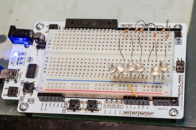
In the tutorial, he sets up a simple 6 LED circuit on a Fredboard (an Arduino compatible board with integrated breadboard). [Akiba] then describes configuring the Vixen sequencer software to control the Arduino, providing simple example code to decode the Vixen serial protocol. Finally [Akiba] shows how to use the ChibiArduino protocol stack to build a wireless illumination system.
[Akiba] has used these tools in many stage performances including with the Wrecking Crew Orchestra (shown above) and the world number 1 flair bartending crew, UPT.
This tutorial is particularly awesome, as it includes both step-by-step videos and a text reference. The videos give a great overview of the process, while the text provides a handy reference to refer to as you hack on your own illumination projects.
Thanks for the writeup [Akiba]! With Christmas just round the corner we hope to see readers using these techniques in their own festive illuminations soon!
The laptop I’m using, found for 50 bucks in the junk bins of Akihabara has a CPU that runs at 2.53GHz. Two billion five hundred and thirty million times every second electrons systematically briefly pulse. To the human mind this is unimaginable, yet two hundred years ago humanity had no knowledge of electrical oscillations at all.
There were clear natural sources of oscillation of course, the sun perhaps the clearest of all. The Pythagoreans first proposed that the earth’s rotation caused the suns daily cycle. Their system was more esoteric and complex than the truth as we now know it and included a postulated Counter-Earth, lying unseen behind a central fire. Regardless of the errors their theory contained, a central link was made between rotation and oscillation.
And rotational motion was exploited in early electrical oscillators. Both alternators, similar to those in use today, and more esoteric devices like the interrupter. Developed by Charles Page in 1838, the interrupter used rocking or rotational motion to dip a wire into a mercury bath periodically breaking a circuit to produce a simple oscillation.
As we progressed toward industrial electrical generators, alternating current became common. But higher and higher frequencies were also required for radio transmitters. The first transmitters had used spark gaps. These simple transmitters used a DC supply to charge a capacitor until it reached the breakdown voltage of the gap between two pieces of wire. The electricity then ionized the air molecules in the gap. Thus allowing current to flow, quickly discharging the capacitor. The capacitor charged again, allowing the process to repeat.
As you can see and hear in the video above spark gaps produce a noisy, far from sinusoidal output. So for more efficient oscillations, engineers again resorted to rotation.
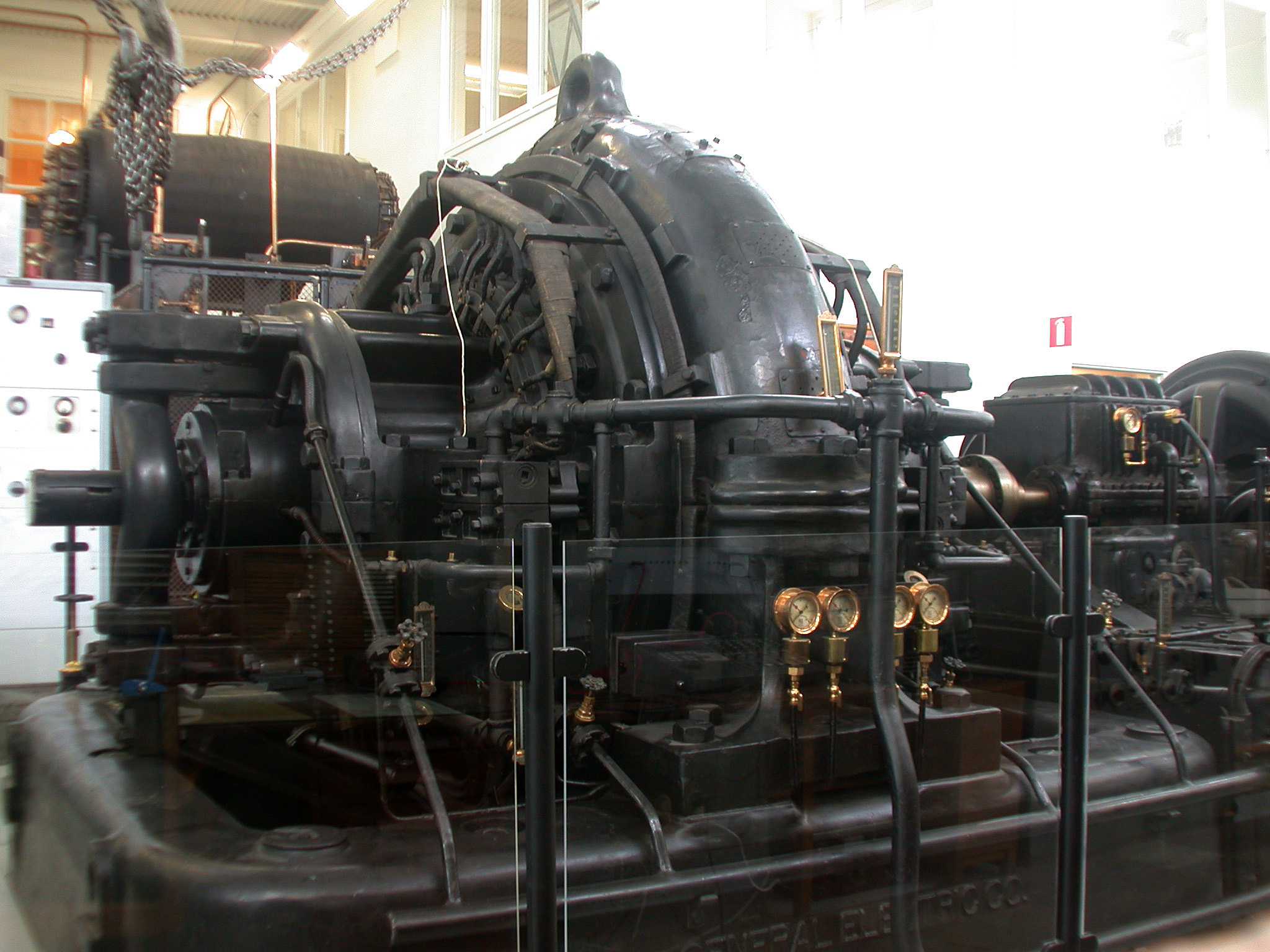
The Alexanderson alternator uses a wheel on which hundreds of slots are cut. This wheel is placed between two coils. One coil, powered by a direct current, produces a magnetic field inducing a current in the second. The slotted disc, periodically cutting this field, produces an alternating current. Alexanderson alternators were used to generate frequencies of 15 to 30 KHz, mostly for naval applications. Amazingly one Alexanderson alternator remained in service until 1996, and is still kept in working condition.
A similar principal was used in the Hammond organ. You may not know the name, but you’ll recognize the sound of this early electronic instrument:
The Hammond organ used a series of tone wheels and pickups. The pickups consist of a coil and magnet. In order to produce a tone the pickup is pushed toward a rotating wheel which has bumps on its surface. These are similar to the slots of the Alexanderson Alternator, and effectively modulate the field between the magnet and the coil to produce a tone.
Amplifying the Oscillation
The operation of a tank circuit (from wikipedia)
So far we have purely relied on electromechanical techniques, however amplification is key to all modern oscillators, for which of course you require active devices. The simplest of these uses an inductor and capacitor to form a tank circuit. In a tank circuit energy sloshes back and forth between an inductor and capacitor. Without amplification, losses will cause the oscillation to quickly die out. However by introducing amplification (such as in the Colpitts oscillator) the process can be kept going indefinitely.
Oscillator stability is important in many applications such as radio transmission. Better oscillators allow transmissions to be packed more closely on the spectrum without fear that they might drift and overlap. So the quest for better, more stable oscillators continued. Thus the crystal oscillator was discovered, and productionized. This was a monumental effort.
Producing Crystal Oscillators
The video below shows a typical process used in the 1940s for the production of crystal oscillators:
Natural quartz crystals mined in Brazil were shipped to the US, and processed. I counted a total of 13 non-trivial machining/etching steps and 16 measurement steps (including rigorous quality control). Many of these quite advanced, such as the alignment of the crystal under an X-Ray using a technique similar to X-Ray crystalography.
These days our crystal oscillator production process is more advanced. Since the 1970s crystal oscillators have been fabricated in a photolithographic process. In order to further stabilize the crystal additional techniques such as temperature compensation (TCXO) or operating the crystal at a temperature controlled by the use of a heating element (OCXO) have been employed. For most applications this has proved accurate enough… Not accurate enough however for the timenuts.
Timenuts Use Atoms
Typical timenut wearing atomic wristwatch
For timenuts there is no “accurate enough”. These hackers strive to create the most accurate timing systems they can, which all of course rely on the most accurate oscillator they can devise.
Many timenuts rely on atomic clocks to make their measurements. Atomic clocks are an order of magnitude more precise than even the best temperature controlled crystal oscillators.
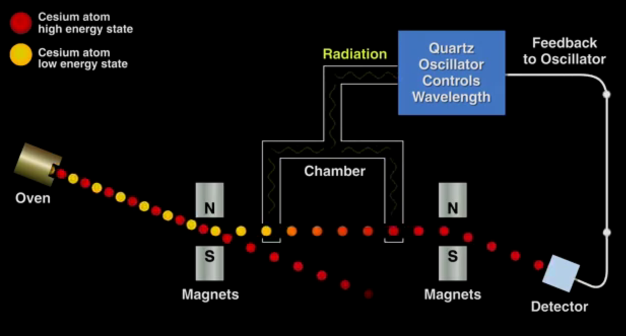
Bill Hammack has a great video describing the operation of a cesium beam oscillator. The fundamental process is shown in the image below. The crux is that cesium gas exists in two energy states, which can be separated under a magnetic field. The low energy atoms are exposed to a radiation source, the wavelength of which is determined by a crystal oscillator. Only a wavelength of exactly 9,192,631,770Hz will convert the low energy cesium atoms to the high energy form. The high energy atoms are directed toward a detector, the output of which is used to discipline the crystal oscillator, such that if the frequency of the oscillator drifts and the cesium atoms are no longer directed toward the detector its output is nudged toward the correct value. Thus a basic physical constant is used to calibrate the atomic clock.
The basic operating principle of a cesium atomic clock
While cesium standards are the most accurate oscillators known, Rubidium oscillators (another “atomic” clock) also provide an accurate and relatively cheap option for many timenuts. The price of these oscillators has been driven down due to volume production for the telecoms industry (they are key to GSM and other mobile radio systems) and they are now readily available on eBay.
With accurate time pieces in hand timenuts have performed a number of interesting experiments. To my mind the most interesting of these is measuring time differences due to relativistic effects. As is the case with one timenut who took his family and a car full of atomic clocks up Mt. Rainier for the weekend. When he returned he was able to measure a 20 nanosecond difference between the clocks he took on the trip and those he left at home. This time dilation effect was almost exactly as predicted by the theory of relativity. An impressive result and an amazing family outing!
It’s amazing to think that when Einstein proposed the theory of special relatively in 1905, even primitive crystal oscillators would not have been available. Spark gap, and Alexanderson alternators would still have been in everyday use. I doubt he could imagine that one day the fruits of his theory would be confirmed by one man, on a road trip with his kids as a weekend hobby project. Hackers of the world, rejoice.
We recently reported on the amateur scientific work of Forrest Mims. Forrest is somewhat unique in being an amateur scientist who has consistently published his work in leading scientific journals. One area of scientific investigation has however attracted amateur scientific contributions of the highest quality almost since its inception, amateur astronomy.
Will Hay – Amateur Astronomer
You’ve likely heard of amateur astronomers like David Levy co-discoverer of the Comet Shoemaker–Levy 9 comet, and citizen science projects like galaxy zoo. But the history of amateur astronomy goes back far further than this, in fact as far back as 1781 William Herschel discovered the planet Uranus while employed as a Musician. Another entertainer of sorts, 1930s British comic actor, Will Hay, also made significant contributions discovering a “Great White Spot” on Saturn in-between films roles. Will was an avid amateur astronomer who regularly published his observations.
His belief that astronomy allows us to see humanity’s place in the universe in its true proportion led him to claim “If we were all astronomers there’d be no more war”.
While Will recorded his observations, hand drawn, in a log book. Modern astronomers digitally image the night sky. Digital cameras are of course optimized around the human visual system (as we recently discussed) making them less than ideal for astrophotography. Hackers have therefore made a number of innovations, one of the more audacious being the removal of the Bayer filter:
Everyone has their favorite process for PCB fabrication, as long as you’re a happy hacker I don’t think it really matters. But in this post I thought it might be interesting to describe my personal process, and some of the options available.
Making your own at home
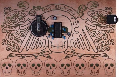
The Dirty Electronics Skull Etching Synth a great looking maskless board.
Etching is the classic PCB fabrication option for the home hacker. It’s been many, many years since I etched a PCBs but it can produce interesting results. Some people don’t like it, and I’d personally tend to avoid it as a messy and finicky process. But, if you only need 1 or 2 layer boards with large features (through-hole components are best of course) it can be a viable option. In some cases, I think etched boards look awesome and are a great fit. One example is the skull etching shown to the right. The oxidation and discoloration of the boards adds to the design aesthetic in this case.
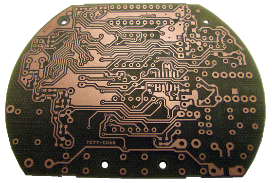
A simple design milled on an Accurate CNC
For those with a bigger budget a professional milling machine might be a viable choice. I’ve used an Accurate CNC in the past (LPKF and others make mills too), but this is an expensive option (no online pricing, but if $10,000 USD is a lot for you don’t bother). The accurate mill is pretty awesome, it can be fitted with a vacuum bed, automatic tool changer and vision system for alignment. The mill can produce high quality two layer boards with all the holes and vias drilled out. The final step of filling the vias is however manual, but compared to etched boards the results are pretty professional (the mill itself uses milled PCBs!). They claim a 0.1mm (4 mil) track size, I’ve never tried tracks this small but surface mount components were not a problem.
While a fun toy, it’s worth considering if you really need a PCB mill. The only case where they’re really valuable is if you want to be able to iterate over a design with less than a days turn around. This can be useful in RF or low noise designs where you might want to experiment with different layouts, but for other projects the price of a good mill can pay for quick turn around (1 or 2 days from order submission to delivery) on a lot of boards.
Commercial Fabrication
Years ago commercial fabrication used to be a very expensive and finicky process. For the most part you’d need to order a full panel putting the service outside of most hobbyists reach. Generating gerbers and drill files to the fabs specification could also be a process fraught with complication.
These days services that aggregate designs onto a single panel and break them out for distribution are common. For my work I mostly stick with OSHPark and SeeedStudio whose services complement each other well. I’ve also used Itead and found them compatible with Seeed (with the added benefit that they supply free boards for open projects).
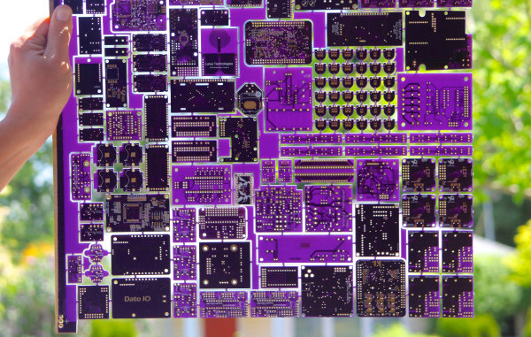
Using OSHPark gives me the warm fuzzies. A child of the hacker community, born out of DorkbotPDX, all OSHPark’s boards are fabbed in the US (check out the great amphour interview for more details). Their services are limited to either 2 or 4 layer boards (always in purple, and always coated with gold (ENIG)), in 6×6 (6 mil traces with 6 mil spacing) or 5×5. I rarely attempt BGA boards so the 2 layer service works out great for me. OSHPark’s minimum order is 3 boards, which is perfect for prototyping. The gold plating also provides a nice finish, which both protects the board from oxidation and provides a nice surface to solder to. The main reason I use OSHPark however is that they’re cheap for small boards and have a relatively fast turn around (I recently purchased 3 tiny 20x15mm boards for $2.40 including shipping which was unbeatable). From OSHPark in the US to the UK my boards take about 2 weeks to arrive. They’ve also automatically upgrade boards to their super-swift service for free when there’s spare capacity. Their service is pretty slick, and provides a rendering of the gerbers prior to ordering as a final check which comes in very handy.
Seeed on the other hand are much cheaper for larger size boards and volume orders. They also provide more color and finishing options. The cheapest option at Seeed is green PCBs with HASL finish (hot air solder leveling). From Seeed, my boards usually take about a month to arrive (there are a few delivery options, but in my experience this is about as fast as it gets and faster shipping services often make using Seeed less attractive).
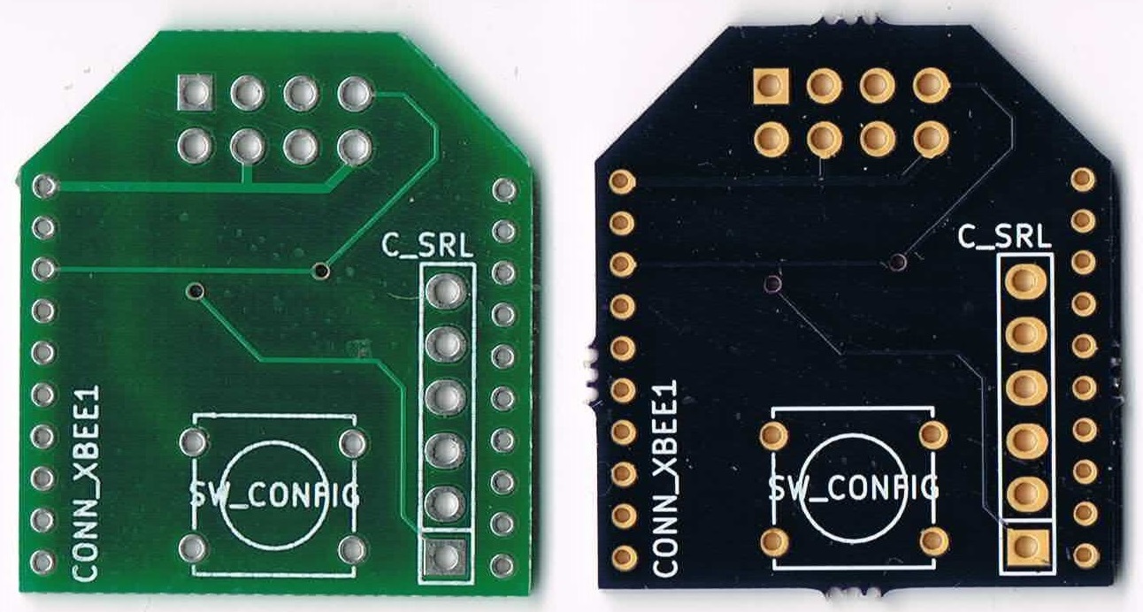
The image to the right shows a couple of very simple boards I had manufactured at both OSHPark and Seeed. I’ve never had a fabrication issues with boards from either service (though I prefer the ENIG finish).
Partly due to the limitations imposed by using commercial fabs I pipeline my projects. I send projects out to fab early in the design process and then switch to another design. When the board comes back I bring it up, bodge as required, and iterate over the layout. This works well with a two-week turn around, so I mostly use OSHPark while prototyping.
My boards also tend to be quite small (Arduino shield size or a little bigger). With small boards like this OSHPark is usually on-par or cheaper than ordering from Seeed (whose minimum quantity is 10 boards). With boards of about 100x100mm or larger I consider Seeed as they become significantly cheaper.
As a hobbyist I also rarely need huge numbers of boards, but for workshops when I need 10 or 20 boards I order from Seeed based on the final iteration of my prototypes. This is not only much cheaper than OSHPark, but I can get boards in a variety of colors to make workshops more interesting too.
This post has described some of the available options and my personal process. I hope it’s been interesting, but I’d love to hear about your favorite fabrication techniques, services and experiences both good and bad too. Please comment below!
 But what, you might ask, makes the 3458A such a significant and desirable instrument? It’s all in the digits. The 3458A is one of the few 8.5 digit multimeters available. It is therefore sensitive to microvolt deflections on 10 volt measurements. It is this ability to distinguished tiny changes on large signals that sets high precision multimeters apart. Imagine weighing an elephant and being able to count the number of flies that land on its back by the change in weight. The 3458A accomplishes a similar feat.