Cascade Failures, Computer Problems, And Ohms Law: Understanding The Northeast Blackout Of 2003

We’ve all experienced power outages of some kind, be it a breaker tripping at an inconvenient time to a storm causing a lack of separation between a tree and a power line. The impact is generally localized and rarely is there a loss of life, though it can happen. But in the video below the break, [Grady] of Practical Engineering breaks down the Northeast Blackout of 2003, the largest power failure ever experienced in North America. Power was out for days in some cases, and almost 100 deaths were attributed to the loss of electricity.

[Grady] goes into a good amount of detail regarding the monitoring systems, software simulation, and contingency planning that goes into operating a large scale power grid. The video explains how inductive loads cause reactance and how the effect exacerbated an already complex problem. Don’t know what inductive loads and reactance are? That’s okay, the video explains it quite well, and it gives an excellent basis for understanding AC electronics and even RF electronic theories surrounding inductance, capacitance, and reactance.

So, what caused the actual outage? The complex cascade failure is explained step by step, and the video is certainly worth the watch, even if you’re already familiar with the event.

It would be irresponsible to bring up the 2003 outage without talking about the Texas ERCOT outages just one year ago– an article whose comments section nearly caused a blackout at the Hackaday Data Center!

Continue reading “Cascade Failures, Computer Problems, And Ohms Law: Understanding The Northeast Blackout Of 2003”

Pour Yourself A Glass Of 100,000 Volts

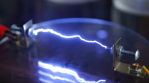
You’d be hard pressed to find a hacker or maker who doesn’t have a soft spot for the tantalizing buzz and snap of a high voltage spark gap, but it remains the sort of project that most of us don’t take on personally. There’s a perceived complexity in building a device capable of shooting a proper spark through several inches of open air, with connotations of exotic components and massive hand-wound coils. Plus, nobody wants to inadvertently singe off their eyebrows.

While the latest video from [Jay Bowles] might not assuage anyone’s fear of performing impromptu electrolysis, it does at least prove that you don’t need to have a laboratory full of gear to produce six figure voltages. In fact, you don’t even need much in the way of electronics: the key components of this DIY Marx generator are made with little more than water and some household items.

This is made possible by the fact that the conductivity of water can be changed depending on what’s been dissolved into it. Straight tap water is a poor enough conductor that tubes of it can be used in place of high voltage resistors, while the addition of some salt and a plastic insulating layer makes for a rudimentary capacitor. You’ll still need wires to connect everything together and some bits of metal to serve as spark gaps, but nothing you won’t find lurking in the parts bin.

Of course, water and a smattering of nails won’t spontaneously generate electricity. You need to give it a bit of a kick start, and for that [Jay] is using a 15,000 volt DC flyback power supply that looks like it may have been built with components salvaged from an old CRT television. While the flyback transformer alone could certainly generate some impressive sparks, this largely liquid Marx generator multiplies the input voltage to produce a serious light show.

We’re always glad to see a new video from the perennially jovial [Jay] come our way. While his projects might not always be practical in the strictest sense, they never fail to inspire a lively discussion about the fascinating applications of high voltage.

Continue reading “Pour Yourself A Glass Of 100,000 Volts”

Solving The Mysteries Of Grounding While Improving A Power Supply

Grounding problems and unwanted noise in electrical systems can often lead to insanity. It can seem like there’s no method to the madness when an electrical “gremlin” caused by one of these things pops its head out. When looking more closely, however, these issues have a way of becoming more obvious. In a recent video, [Fesz Electronics] shows us how to investigate some of these problems by looking at a small desktop power supply, modelling it in LTSpice, and reducing the noise on the power supply’s output.

While everything in this setup is properly grounded, including the power supply and oscilloscope, the way the grounding systems interact can contribute to the high amount of noise. This was discovered by isolating the power supply from earth ground using electrical tape (not recommended as a long-term solution) and seeing that the noise was reduced. However, the ripple increased substantially, so a more permanent fix was needed. For that, the power supply was modelled in LTSpice. This is where a key discovery was made: since all the parts of the power supply aren’t ideal, noise can be introduced from the actual real-life electrical behavior of some of the parts. In this case, it was non-ideal capacitance in the transformer.

According to the model, this power supply could be improved by adding a larger capacitor across the output leads, and also by increasing their inductance. A large capacitor was soldered in the power supply and an iron ferrule was added, which decreased the noise level from 100 mV to around 20. Still not perfect, but a much needed improvement to the simple power supply. If, on the other hand, you want to make sure you eliminate that transformer’s capacitance completely, you can always go with a transformerless power supply. That carries other risks, though.

Continue reading “Solving The Mysteries Of Grounding While Improving A Power Supply”

Everything You Didn’t Know You Were Missing About Bias Tees

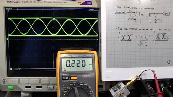
Do you need a bias tee? If you want to put a DC voltage on top of an RF signal, chances are that you do. But what exactly are bias tees, and how do they work?

If that’s your question, [W2AEW] has an answer for you with this informative video on the basics of bias tees. A bias tee allows a DC bias to be laid over an RF signal, and while that sounds like a simple job, theory and practice often deviate in the RF world. The simplest bias tee would have a capacitor in series with the RF input and output to pass AC but block DC from getting out the input, and a DC input with a series inductance to prevent RF from getting into the DC circuit. Practical circuits are slightly more complicated, and [W2AEW] covers all you need to know about how real-world bias tees are engineered. He also gives some use cases for bias tees, from sending DC signals up a feed line to control an antenna tuner or rotator to adding a DC bias to a high-speed serial line.

It’s an interesting circuit, and we learned a lot, which is par for the course with [W2AEW]’s videos. Check out some of his other offerings, like a practical guide to the mysteries of Smith charts, or his visualization of how standing waves work.

Continue reading “Everything You Didn’t Know You Were Missing About Bias Tees”

Going Digital: Upgrading A Boat’s Analog Gauge

The odds are that many of you do not own a boat that you get to tinker around with. [Mavromatic] recently acquired one that had — much to his consternation — analog gauges. So in order to get his ship ship-shape, he built himself a custom digital gauge to monitor his vessel’s data.

Restricted to the two-inch hole in his boat’s helm, trawling the web for displays turned up a 1.38-inch LCD display from 4D Systems. Given the confined space, a Teensy 3.2 proved to be trim enough to fit inside the confined space alongside a custom circuit board — the latter of which includes some backup circuits if [mavromatic] ever wanted to revert to an analog gauge.

Two days of acclimatization to the display’s IDE and he had enough code to produce a functional display right when the parts arrived.

Continue reading “Going Digital: Upgrading A Boat’s Analog Gauge”

A Flexible Sensor That Moves With You

If you have a project in mind that requires some sort of gesture input or precise movements, it might become a nettlesome problem to tackle. Fear this obstacle no longer: a team from the Wyss Institute for Biologically Inspired Engineering at Harvard have designed a novel way to make wearable sensors that can stretch and contort with the body’s natural movements.

The way they work is ingenious. Layers of silicone are sandwiched between two lengths of silver-plated conductive fabric forming — by some approximation — a capacitance sensor. While the total surface area doesn’t change when the sensor is stretched — how capacitance sensors normally work — it does bring the two layers of fabric closer together, changing the capacitance of the band in a proportional and measurable way, with the silicone pulling the sensor back into its original shape as tension relaxes. Wires can be attached to each end of the band with adhesive and a square of thermal film, making an ideal sensor to detect the subtlest of muscle movements.

Continue reading “A Flexible Sensor That Moves With You”

Gyrators: The Fifth Element

A few years ago, there was a stir about a new fundamental component called a memristor. That wasn’t the first time a new component type was theorized though. In 1948 [Bernard Tellegen] postulated the gyrator. While you can’t buy one as a component, you can build one using other components. In fact, they are very necessary for some types of design. Put simply, a gyrator is a two-terminal device that inverts the current-voltage characteristic of an electrical component. Therefore, you can use a gyrator to convert a capacitor into an inductor or vice versa.

Keep in mind, the conversion is simply the electrical properties. Normally, current leads voltage in a capacitor and lags it in an inductor, and that’s what a gyrator changes. If you use a gyrator and a capacitor to make a virtual inductor, that inductor won’t magnetically couple to another inductor, real or simulated. There’s no magnetic field to do so. You also don’t get big voltage spikes caused by back EMF, which depending on your application could be a plus or a minus. But if you need an ungainly inductor in a circuit for its phase response, a gyrator may be just the ticket.

Continue reading “Gyrators: The Fifth Element”