DIY SSR For Mains Switching

Typical power strips have their sockets tightly spaced. This makes it cumbersome to connect devices whose wall warts or power bricks are bulky — you end up losing an adjoining socket or two. And if the strip has a single power switch, you cannot turn off individual devices without unplugging them.

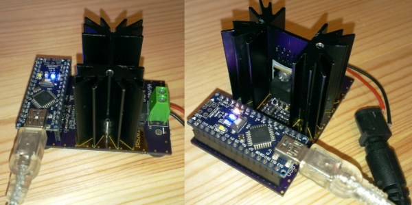
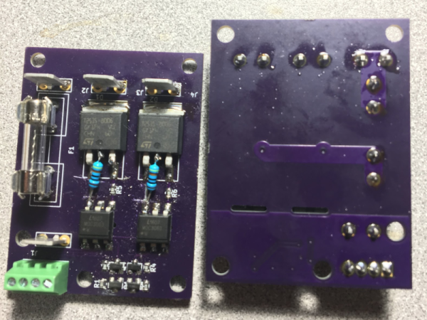
Planning to tackle both problems together, [Travis Hein] built himself some custom Dual SSR Controlled Socket Outlets for his workbench. He also decided to add remote switching ability so he could turn off individual sockets via a controller, Raspberry Pi, smartphone app or most ideally, a nice control panel on his desk consisting of a bank of switches.

The easiest solution for his problem would have been to just buy some off-the-shelf SSR or relay modules and wire them up inside his sockets. But he couldn’t find any with the features he wanted, and SSR’s were a little bit on the expensive side. Also, we wouldn’t have a project to write about – sometimes even the simple ones can show us a thing or two.

For starters, he walks us through a quick and simplified primer on figuring out thermal dissipation for the triacs which will be used on his boards. This is tricky since the devices are connected directly to utility voltage so he needs to take care of track clearances, mechanical separation as well as safety. However, for his first board prototypes, he did not add any heat sinking for the triacs, thereby limiting their use to low current loads. Since the SSR also needs to have a wide control voltage range, he describes how the two transistor constant-current input block works to limit opto-triac LED current over a range of 2 V to 30 V.

Before he moves on to his next prototype, [Travis] is looking for feedback to improve his design, make it safer, and figure out if it can pass safety protocols. Let him know via comments below.

Circuit VR: Sink Or Swim With Current Sources

If you got your start in electronics sometime after 1980 your first project might well have been to light up an LED. Microcontroller projects often light up an LED, too, and a blinking LED is something of the “hello world” program for embedded systems. If you tried lighting up your LED with a 9 V battery directly — not that you’d admit to it — you found it would light up. Once, anyway. The excess current blows up the LED which is why you need a current-limiting resistor. However, those current limiting resistors are really a poor excuse for a current source or sink. In many applications, you need a real current source and luckily, they aren’t hard to create.

As always with Circuit VR, we’ll be using LT Spice to examine the circuits. If you need a quick tutorial, start here and come back after that. If you use Linux, don’t be dismayed. I run LT Spice under WINE and it works great. You can find all the Spice files on GitHub.

Continue reading “Circuit VR: Sink Or Swim With Current Sources”

Milliohm Meter Version 1.5

A milliohm meter is a very handy piece of test equipment. Most hand-held multimeters cannot measure low resistances and bench meters that can, are usually quite expensive. [barbouri] has shared details of his milliohm meter build on his blog post, and it looks pretty nice.

When using a single pair of leads to measure very low ohms, the resistance of the measuring wires and voltage drops across the various joints become substantial enough to invalidate your measurement. The solution is to use the “Kelvin method” or 4-wire measurement. This involves passing a highly stable current derived from a temperature compensated constant-current source through the unknown resistance, and then using another pair of leads to measure the voltage drop across the resistor, which then gets displayed as a resistance on a voltmeter.

The finished project not only looks good, but is able to measure up to 2Ω with a resolution of 0.0001Ω (that’s 0.1mΩ). The project is originally designed by [Louis] from [Scullcom Hobby Electronics] and [barbouri]’s second iteration adds an improved board layout to the original project.

Continue reading “Milliohm Meter Version 1.5”

A Peek Under The Hood Of The 741 Op-Amp

First introduced as an IC back in 1968, but with roots that go back to 1941, the 741 has been tweaked and optimized over the years and is arguably the canonical op-amp. [Ken Shirriff] decided to take a look inside everybody’s favorite op-amp, and ended up with some good-looking photomicrographs and a lot of background on the chip.

can
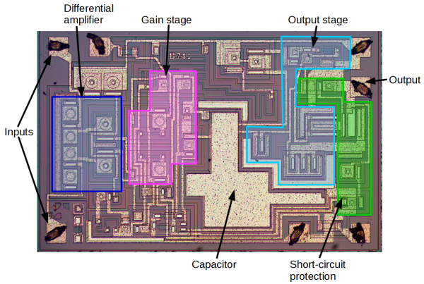
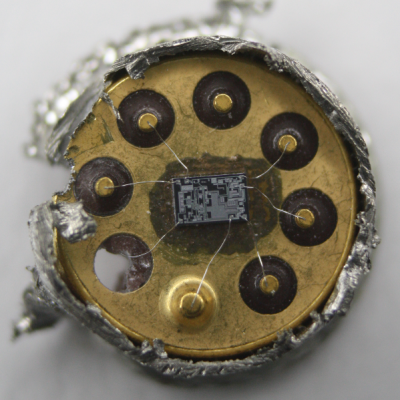
Rather than risk the boiling acid method commonly used to decap epoxy-potted ICs, [Ken] wisely chose a TO-99 can format to attack with a hacksaw. With the die laid bare for his microscope, he was able to locate all the major components and show how each is implemented in silicon. Particularly fascinating is the difference between the construction of NPN and PNP transistors, and the concept of “current mirrors” as constant current sources. And he even whipped up a handy interactive chip viewer – click on something in the die image and find out which component it is on the 741 schematic. Very nice.

We’ve seen lots of chip decappings before, including this reveal of TTL and CMOS logic chips. It’s nice to see the guts of the venerable 741 on display, though, and [Ken]’s tour is both a great primer for the newbie and a solid review for the older hands. Don’t miss the little slice of history he included at the end of the post.

Using A Voltage Regulator As A Constant Current Source

[Afroman] contacted us to share his new video on the LM317. The humble LM317 adjustable voltage regulator is everywhere. From wifi routers, to high spec lab equipment. Given a noisy input and a variable load, a voltage regulator will give a nice clean, stable output voltage. We’ve covered the basic operation and usage of the LM317 many times. But even the most common of parts can be used in new and interesting ways.

In his video [Afroman] describes how the LM317 can be used to regulate current rather than voltage to provide a constant current source under varying load. This can useful for a number of applications including driving LEDs and laser diodes. While this circuit may not be as efficient as an LED driver module or a switching solution the LM317 is cheap and readily available. [Afroman] also describes how the circuit works in detail allowing us to enjoy this ubiquitous part in this slightly unusual application.

Continue reading “Using A Voltage Regulator As A Constant Current Source”

Arduino Electronic Load

A Simple Programmable Electronic Load Using The Arduino

Some projects are both educational and useful. We believe that [Jasper’s] Arduino based electronic load is one of those project.

[Jasper’s] electronic load can not only act as a constant current load, but also as a constant power and constant resistive load as well. The versatile device has been designed for up to 30V, 5A, and 15W. It was based on a constant current source that is controlled by a DAC hooked up to the Arduino. By measuring both the resulting voltage and current of the load, the system can dynamically adapt to achieve constancy. While we have seen other Arduino based constant loads before, [Jasper’s] is very simple and straight forward compartively. [Jasper] also includes both the schematic and Arduino code, making it very easy to reproduce.

There are tons of uses for a voltage controlled current source, and this project is a great way to get started with building one. It is an especially great project for putting together your knowledge of MOSFET theory and opamp theory!