ACK1 Makes Getting To Know The ATtiny1616 Easy

Many readers will be familiar with Microchip’s ATtiny85, which has been a popular choice for DIY projects in the past for its low price and (for the time) small size. But those looking for a more modern and capable 8-bit chip may find the ATtiny1616-MNR of interest. It offers expanded flash storage, more GPIO, and ditches SPI programming in favor of UPDI — a protocol that can be done using nothing more than an USB-UART converter and a resistor.

The contents of the ACK1 kit
What’s in the kit if you buy it.

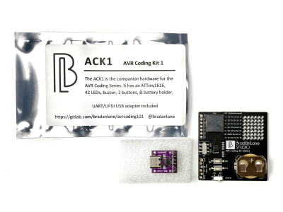
But here’s the catch: the new chip is only available in SMD and there are far fewer tutorials for it! That’s why [Bradán Lane] has created ACK1, a cute little AVR Coding Kit for those of us who want to play with the ATtiny1616 and a companion for his free and open-source course.

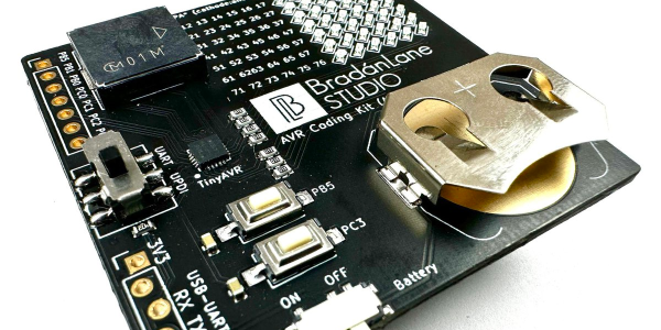
The board contains an array of 6 by 7 LEDs in a charlieplexed configuration, a large piezo buzzer, two push buttons, an on/off switch, and a CR2032 battery holder to keep it on without the need for a cable. The kit looks gorgeous in its white-on-black theme with gold plated contacts and can be had for $20 on Tindie at the time of writing.

The ATtiny1616 itself runs at up to 20 MHz and has 17 GPIO pins, 16 KiB of flash storage, 2 KiB of RAM, and 256 bytes of EEPROM for configuration — making it roughly on par with the original Arduino Uno.

The course that goes hand-in-hand with the ACK1 is all about the features of the ATtiny1616, from the basics of using the programmer to reading the buttons, using timers, driving the charlieplexed LEDs, storing data in the EEPROM and much more. Though it does not cover the basics of C, the course is free, and even licensed MIT, so that anyone can share it and improve upon it.

If you enjoy seeing beautiful microcontrollers, you’ll definitely want to see the stylish Uno Plus+.

The Science Behind Boost Converters

[Ludic Science] shows us the basic principles that lie behind the humble boost converter. We all take them for granted, especially when you can make your own boost converter or buy one for only a few dollars, but sometimes it’s good to get back to basics and understand exactly how things work.

The circuit in question is probably as simple as it gets when it comes to a boost converter, and is not really a practical design. However it helps visualize what is going on, and exactly how a boost converter works, using just a few parts, a screw, enameled wire, diode, capacitor and a push button installed on a board.

The video goes on to show us the science behind a boost converter, starting with adding a battery from which the inductor stores a charge in the form of an electromagnetic field. When the button is released, the magnetic field collapses, and this causes a voltage in the circuit which is then fed through a diode and charges the capacitor a little bit. If you toggle the switch fast enough the capacitor will continue to charge, and its voltage will start to rise. This then creates a larger voltage on the output than the input voltage, depending on the value of the inductor. If you were to use this design in a real life application, of course you would use a transistor to do the switching rather than a push button, it’s so much faster and you won’t get a sore finger.

This is very basic stuff,  but the video gives us a great explanation of what is happening in the circuit and why. If you liked this article, we’re sure you’ll love Hackaday’s own [Jenny List] explain everything you need to know about inductors.

(updated thanks to [Unferium] – I made a mistake about the magnetic field collapsing when the button is pressed , When in reality it’s when the button is released that this happens. Apologies for confusion.)

Continue reading “The Science Behind Boost Converters”

Crappy Robots And Even Crappier Electronics Kits

Robots and DIY electronics kits have a long history together. There probably isn’t anyone under the age of forty that hasn’t had some experience with kit-based robots like wall-hugging mouse robots, a weird walking robot on stilts, or something else from the 1987 American Science and Surplus catalog. DIY robot kits are still big business, and walking through the sales booths of any big Maker Faire will show the same ideas reinvented again and again.

[demux] got his hands on what is possibly the worst DIY electronics kit in existence. It’s so incredibly bad that it ends up being extremely educational; pick up one of these ‘introduction to electronics’ kits, and you’ll end up learning advanced concepts like PCB rework, reverse engineering, and Mandarin.

Continue reading “Crappy Robots And Even Crappier Electronics Kits”

DIY Heatsinking PCBs

pcb heatsink

We have covered many do it yourself PCBs before, but this video guide adds an easy way to sink heat from high power devices, which we think you might find handy.

It is a very simple process that [CNLohr] uses to keep his small RGB LED projects from overheating. It starts by using a readily available silicone thermal sheet as the substrate by applying it to copper foil. He then applies a toner-transfer circuit pattern to the copper by running the pair through a modified laminator a few times. He makes note that you have to apply the plastic backing side of the silicone sheet to the copper foil to prevent the laminator from chewing it up.

After the typical ferric chloride etching process is complete, he then uses 220 grit sandpaper to remove the toner pattern. Often steel wool is used, but because of the sensitive nature of the silicone, sandpaper works better to avoid peeling up traces.

We have featured [CNLohr] before, as he does some top-notch tutorials in his workshop — which makes for both a fascinating and distracting backdrop for the videos. This one is a bit long (~20 minutes), but is very thorough and goes through the entire process from start to finish. Check it out after the break.

Continue reading “DIY Heatsinking PCBs”

How-to: Digital Picture Frame, 100% DIY

frontii

There are a ton of digital picture frame tutorials out there. Most are old laptops with crafty case reconfigurations that fit a photo frame profile.

We set out to build a 100% DIY, scratch-built digital picture frame. Our frame has a 12bit color LCD, gigabytes of storage on common, FAT-formatted microSD cards, and you can build it at home. We’ve got the details below.

Continue reading “How-to: Digital Picture Frame, 100% DIY”

Accelerometer Controlled Pong

[youtube=http://www.youtube.com/watch?v=jYVgXYtxk4E]

[Perry’s] awesome AcceLED Pong project gives new life to a classic game by adding acceleration-based control. The pong paddles are moved by tilting the circuit left or right. Motion is measured by an ADXL203 dual axis accelerometer, and an ATMEGA32 microcontroller converts acceleration into ball and paddle movement. The game display is a three-color SparkFun 8×8 LED matrix with serial interface.

[Perry] also used a similar setup to make a USB LED spectrum analyzer fed by the Linux XMMS media player.