Color(ing) Computer Needs No Batteries

While Radio Shack did have the Color Computer, we don’t think they had this in mind. [Pepepépepe] has some coloring book pages and simple rules that let you simulate logic circuits using a crayon. The downloadable ‘zine has hand-written instructions and several examples.

Keep in mind, this is a computer in the same way the old logic kits in the 1960s were computers. They are really demonstrations of digital logic circuits. To work the “computers”, you pick two colors, one for a square and the other for a circle. You color pathways until you reach a “nory.” The nory, which looks suspiciously like a slingshot with eyes, has a special rule. If both branches of the nory have your circle color on them, the output of the nory will be the square color. Otherwise, the color coming out is the circle color.

Continue reading “Color(ing) Computer Needs No Batteries”

An ATTiny board that one of the students developed for this project, etched on single-sided FR4.

Electronics And C++ Education With An ATTiny13

When [Adam, HA8KDA] is not busy with his PhD studies, he mentors a group of students interested in engineering. To teach them a wide range of topics, he set out to build a small and entertaining embedded project as they watch and participate along the way. With this LED-adorned ATTiny13A project, [Adam] demonstrated schematic and PCB design, then taught C++ basics and intricacies – especially when it comes to building low-footprint software – and tied it all together into a real-world device students could take home after the project. His course went way beyond the “Hello world”s we typically expect, and some of us can only wish for a university experience like this.

He shares the PCB files and software with us, but also talks about the C++20 framework he’s developed for this ATTiny. The ATTiny13A is very cheap, and also very limited – you get 1K of ROM and 64 bytes of RAM. This framework lets you make good use of it, providing the basics like GPIO wiggling, but also things like low-power operation hooks, soft PWM with optional multi-phase operation support and EEPROM access. Students could write their own animations for this device, and he includes them in the repo, too!

In educational projects, it pays to keep code direct and clean, cruft-less and accessible to students. These are the things you can only achieve when you truly understand the tools you’re working with, which is the perfect position for teaching about them! [Adam] intends to show that C++ is more than suitable for low-resource devices, and tells us about the EEPROM class code he wrote – compiling into the same amount of instructions as an Assembly implementation and consuming the same amount of RAM, while providing compile-time checks and fail-safe syntax.

We’ve talked about using C++ on microcontrollers before, getting extra compile-time features without overhead, and this project illustrates the concept well. [Adam] asks us all, and especially our fellow C++ wizards, for our opinions on the framework he designed. Could you achieve even more with this simple hardware – make the code more robust, clean, have it do more within the limited resources?

What could you build with an ATTiny13, especially with such a framework? A flashy hairclip wearable, perhaps, or a code-learning RF-remote-controlled outlet. We’ve also seen a tiny camera trigger for endurance races,, a handheld Flappy Bird-like console, and many more!

Two pairs of boards described in the article, with toggle switches and RCA jacks, shown interconnected, LEDs on all four boards lit up.

Boards For Playful Exploration Of Digital Protocols

Teaching people efficiently isn’t limited to transmitting material from one head to another — it’s also about conveying the principles that got us there. [Mara Bos] shows us a toolkit (Twitter,
nitter link
) that you can arm your students with, creating a small playground where, given a set of constraints, they can invent and figure communication protocols out on their own.

This tool is aimed to teach digital communication protocols from a different direction. We all know that UART, I2C, SPI and such have different use cases, but why? Why are baud rates important? When are clock or chip select lines useful? What’s the deal with the start bit? We kinda sorta figure out the answers to these on our own by mental reverse-engineering, but these things can be taught better, and [Mara] shows us how.

Gently guided by your observations and insights, your students will go through defining new and old communication standards from the ground up, rediscovering concepts like acknowledge bits, bus contention, or even DDR. And, as you point out that the tricks they just discovered have real-world counterparts, you will see the light bulb go on in their head — realizing that they, too, could be part of the next generation of engineers that design the technologies of tomorrow.

Continue reading “Boards For Playful Exploration Of Digital Protocols”

REMOTICON 2021 // Jay Doscher Proves Tinkercad Isn’t Just For Kids

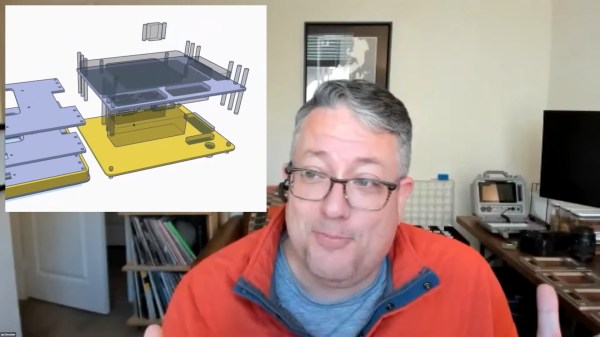
We invited [Jay Doscher] to give us a view into his process designing 3D printed parts for the impressive array of cyberdecks we’ve covered since 2019.

[Jay] got his start as a maker through woodworking in high school, getting satisfaction from bringing something from idea to reality. After a more recent class in blacksmithing and ax-making showed him what he could do when really focused, his hardware hacking really took off and his line of cyberdecks and other portable computers was born.

If you’ve heard of Tinkercad, you probably think it’s just for kids. While designed as an educational tool, [Jay] found that Autodesk’s younger sibling to the professionally powered (and priced) Fusion 360 had everything needed for making cyberdecks. If you’re willing to work around a few limitations, at the low-low price of free, Tinkercad might be right for you too.

What limitations? To start, Tinkercad is only available in a browser and online. There’s also no guarantee that it will remain free, but [Jay] notes that with its educational focus that is likely to remain the case. There is no library of common components to import while modeling. And, when your model is complete the options for exporting are limited to 2D SVGs and 3D STL, OBJ, and gaming-focused GBL formats. [Jay] has converted those to other formats for laser cutting and the STEP file a machine shop is expecting but admits that it’s something that adds complexity and is an annoyance.

back7-TinkerCad-Alignment

In the talk, [Jay] discusses moving from his initial “cringy” explorations with Tinkercad, to his first cyberdeck, a little history on that term, and the evolution of his craft. It’s mostly a hands-on demo of how to work with Tinkercad, full of tips and tricks for the software itself and implications for 3D printing yourself, assembly, and machining by others.

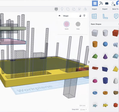
While quite limited, Tinkercad still allows for boolean operations to join two volumes or the subtraction of one from another. [Jay] does a wonderful job of unpeeling the layers of operations, showing how combinations of “solids” and “holes” generated a complex assembly with pockets, stepped holes for fasteners, and multiple aligned parts for his next cyberdeck. Even if you already have a favorite CAD tool, another approach could expand your mind just like writing software in Strange Programming Languages can.

Continue reading “REMOTICON 2021 // Jay Doscher Proves Tinkercad Isn’t Just For Kids”

Cerberus 2080 — Three-Headed Retro Computing Project

For seven months, [Bernardo Kastrup] at [TheByteAttic] has been realizing his childhood dream of building his own computer. It was this dream that steered him into the field of computer design at the age of 17. After thirty years in the industry, he finally has some time to design the computer he dreamt about as a kid. His requirements are ambitious: fully open design, gate-level details, thru-hole or PLCC for easy hacking, well-established processors with existing tool chains, low-cost development tools for CPLDs, no FPGA, standard ITX case compatible, and so on. He quite reasonably decides to use more modern electronics for video (VGA), keyboard (PS/2), and program storage (flash drive). Along the way, he chooses to put three processors on the board instead of one:

  • Zilog Z84C0010 (Z80)
  • WDC W65C0256 (6502)
  • AVR ATMEGA328 (RISC Controller)

When coming up with the concept and requirements, [Bernardo] had a fictitious alternate history in mind — one where there were follow-ups to the ZX80, PET/CBM, or TRS-80 from the late 1970s that were extensions to the original systems. But he also wanted a clean design, without cost-cutting gimmicks, in order to make it easier for learners to focus on computing itself — a didactic architecture, as he describes it. Turn the crank for seven long months, and we have the Cerberus 2080. [Bernardo] has put the design on GitHub, and made a video series out of the whole process, of which the introduction video is below the break. There’s even an online emulator developed by retro hacker  [Andy Toone].

We wrote about the 6502-based ERIC-1 project back in 2014 which shared the bus with an ATMEGA simulating ROM. The Minty Z80 project from 2019 also uses a similar technique. Thanks to [Frédéric] for sending us the tip.

Continue reading “Cerberus 2080 — Three-Headed Retro Computing Project”

Minimal UART Computer

[Carsten] spent over a year developing a small CPU system, implementing his own minimalist instruction set entirely in TTL logic. The system uses a serial terminal interface for all I/O, hence the term UART in the title. [Carsten] began building this computer on multiple breadboards, which quickly got out of hand.

He moved the design over to a PCB, but he was still restless. This latest revision replaces EEPROM with cheaper and easier to use CMOS Flash chips, and the OS gains a small file system manager. As he says in the video, his enemy is feature creep.

Tetris on the UART Computer

In addition to designing this CPU project, [Carsten] built an assembler and wrote a substantial operating system and various demo programs and games. He not only learned KiCAD to make this board, but also taught himself to use an auto-router. The KiCAD design, Gerbers, and BOM are all provided in his repository above. ROM images and source code are provided, as well as a Windows cross-assembler. But wait – there’s more. He also wrote a cycle exact emulator of the CPU, which, as he rightfully brags, comes in at under 250 lines of C++ code. This whole project is an amazing undertaking and represents a lot of good work. We hope he will eventually release the assembler project as well, in case others want to take on the challenge of building it to run under Linux or MacOS. Despite this, the documentation of the Minimal UART Computer is excellent.

[Carsten] claims the project has finally passed the finish line of his design requirements, but we wonder, will he really stop here? Do check out his YouTube channel for further informative videos. And thanks to [Bruce] for sending in the tip.

Continue reading “Minimal UART Computer”

A Big Set Of Logic Gates For Teaching The Basics

Teaching students about logic gates is often done in two parts, once on the whiteboard for the theory, and again on the breadboard for the practice. [shurik179] wasn’t a fan of the abstraction between easy-to-understand symbols on the whiteboard, and small IC packages full of many gates in reality. Instead, he built a set of real-world logic gates that can be wired together as a teaching tool.

Each “gate’ consists of a PCB roughly the size of a business card that features LEDs to indicate the state of its inputs and outputs, and a silkscreen indicating the name and symbol of the gate in question. There’s also a master PCB, which features three seed values, A, B, and C, to feed into the system. Students can set these values to 1 or 0, and feed them into the gates, which are wired together with 3-conductor servo cables, and observe the input on the built-in LEDs.

It’s a great way to demonstrate logic gates in the classroom. The design also allows the PCBs to be flipped over to show the actual electronic components responsible for implementing the logic, serving as a great bridge towards better understanding of real electronic design. Of course, it’s not the only way to learn – even Fallout 4 has a fully fledged logic toolkit these days!