Flash Memory: Caveat Emptor

We all love new tech. Some of us love getting the bleeding edge, barely-on-the-market devices and some enjoy getting tech thirty years after the fact to revel in nostalgia. The similarity is that we assume we know what we’re buying and only the latter category expects used parts. But, what if the prior category is getting used parts in a new case? The University of Alabama in Huntsville has a tool for protecting us from unscrupulous manufacturers installing old flash memory.

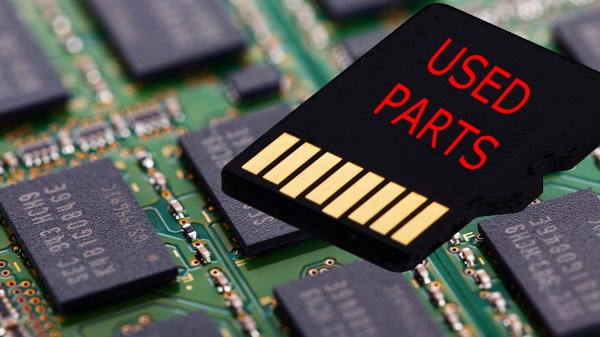
Flash memory usually lasts longer than the devices where it is installed, so there is a market for used chips which are still “good enough” to pass for new. Of course, this is highly unethical. You would not expect to find a used transmission in your brand new car so why should your brand new tablet contain someone’s discarded memory?

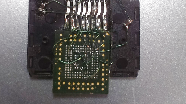
The principles of flash memory are well explained by comparing them to an ordinary transistor, of which we are happy to educate you. Wear-and-tear on flash memory starts right away and the erase time gets longer and longer. By measuring how long it takes to erase, it is possible to accurately determine the age of chip in question.

Pushing the limits of flash memory’s life-span can tell a lot about how to avoid operation disruption or you can build a flash drive from parts you know are used.

Soldering Saves Data From Waterlogged Laptop

What happens when you drop your laptop in the pool? Well, yes, you buy a new laptop. But what about your data. You do have backups, right? No, of course, you don’t. But if you can solder like [TheRasteri] you could wire into the flash memory on the motherboard and read it one last time. You can see the whole exploit in the video below.

There’s really three tasks involved. First is finding the schematic and board layout for motherboard. Apparently, these aren’t usually available from the manufacturer but can be acquired in some of the seedier parts of the Internet for a small fee. Once you have the layout, you have to arrange to solder wires to the parts of the flash memory you need to access.

Continue reading “Soldering Saves Data From Waterlogged Laptop”

Home-Brew Ruby Laser Packs A Wallop

In the past half-century, lasers have gone from expensive physics experiments using rods of ruby to cheap cutting or engraving tools, and toys used to tease cats. Advances in physics made it all possible, but it turns out that ruby lasers are still a lot of fun to play with, if you can do it without killing yourself.

With a setup that looks like something from a mad scientist movie set, [styropyro]’s high-powered laser is a lot closer to the ray gun of science fiction than the usual lasers we see, though hardly portable. The business end of the rig is a large ruby rod nestled inside a coiled xenon flash lamp, which in turn is contained within a polished reflector. The power supply for the lamp is massive — microwave oven transformers, a huge voltage multiplier, and a bank of capacitors that he says can store 20 kilojoules. When triggered by a high-voltage pulse from a 555 oscillator and an old car ignition coil, the laser outputs a powerful pulse of light, which [styropyro] uses to dramatic effect, including destroying his own optics. We’d love to hear more about the power supply design; that Cockcroft-Walton multiplier made from PVC tubes bears some exploration.

Whatever the details, the build is pretty impressive, but we do urge a few simple safety precautions. Perhaps a look at [Ben Krasnow]’s 8-kJ ruby laser would help.

Continue reading “Home-Brew Ruby Laser Packs A Wallop”

Trouble Flashing Your ESP8266? Meet DIO And QIO

[Pete] was building a hot tub controller, using a WEMOS board based on the venerable ESP8266. After assembly, the board was plugged into USB and [Pete] hit the flash button. No dice. Investigation with some terminal software indicated a checksum error.

Assuming the board was dead, [Pete] grabbed another — and suffered the same problem.  The WEMOS boards wouldn’t program, but other boards had no issues. Sensing that something may be amiss, further research was in order. A forum post turned up discussing different programming modes for the ESP8266.

It turns out that there are different types of flash used with the ESP8266, and the correct programming mode must be selected for a given hardware setup. These modes are known as DIO and QIO, meaning “dual IO” and “quad IO” respectively. This refers to the number of IO line used to talk to the flash memory. There are also further modes, known as DOUT and QOUT. It’s important to identify the modes supported by the flash chip on board, by looking at the datasheet. Obviously this can be difficult on some pre-built modules, so experimentation is the key here.

With the wrong mode selected, writes to the flash will fail, and reading back will turn up a checksum error. It’s a simple matter of changing a line in the make file and trying different modes, to see which one works. This forum post has a more in-depth coverage of the issue. 

By choosing different flash memory parts and selecting the DIO or DOUT modes, it’s actually possible to free up more GPIO pins as well. This knowledge is handy when optimizing ESP8266 designs for memory speed or maximum IO flexibility. It’s a good lesson that it always pays to look at the datasheet to get the best out of your parts.

Bodging On More Flash Memory

[Curmudegeoclast] found himself running out of flash memory on a Trinket M0 board, so he decided to epoxy and fly-wire a whopping 2 MB of extra flash on top of the original CPU.

We’ll just get our “kids these days” rant out of the way up front: the stock SAMD21 ARM chip has 256 kB (!) of flash to begin with, and is on a breakout board with only five GPIO pins, for a 51 kB / pin ratio! And now he’s adding 2 MB more? That’s madness. The stated reason for [Curmudegeoclast]’s exercise is MicroPython, which takes up a big chunk of flash just for the base language. We suspect that there’s also a fair amount of “wouldn’t it be neat?” in the mix as well. Whatever.

The hack is a classic. It starts off with sketchy wires soldered to pins and breadboarded up with a SOIC expander board. Following that proof of concept, some degree of structural integrity is brought to the proceedings by gluing the flash chip, dead-bug, on top of the microcontroller. We love the (0805?) SPI pullup resistor that was also point-to-point soldered into place. We would not be able to resist the temptation to entomb the whole thing in hot glue for “long-term” stability, but there are better options out there, too.

This hack takes a minimalist board, and super-sizes it, and for that, kudos. What would you stuff into 2 MB of free flash on a tiny little microcontroller? Any of you out there using MicroPython or CircuitPython care to comment on the flash memory demands? 256 kB should be enough for anyone.

EMMC To SD Hack Rescues Data From A Waterlogged Phone

How do I get the data off this destroyed phone? It’s a question many of us have had to ponder – either ourselves or for friends or family. The easy answer is either spend a mint for a recovery service or consider it lost forever.  [Trochilidae] didn’t accept either of those options, so he broke out the soldering iron and rescued his own data.

A moment’s inattention with a child near a paddling pool left [Trochilidae’s] coworker’s wife with a waterlogged, dead phone. She immediately took apart the phone and attempted to dry it out, but it was too late. The phone was a goner. It also had four months of photos and other priceless data on it. [Trochilidae] was brought in to try to recover the data.

The phone was dead, but chances are the data stored within it was fine. Most devices built in the last few years use eMMC flash devices as their secondary storage. eMMC stands for Embedded Multimedia Card. What it means is that the device not only holds the flash memory array, it also contains a flash controller which handles wear leveling, flash writing, and host interface. The controller can be configured to respond exactly like a standard SD card.

The hard part is getting a tiny 153 ball BGA package to fit into an SD card slot.  [Trochilidae] accomplished that by cutting open a microSD to SD adapter. He then carefully soldered the balls from the eMMC to the pins of the adapter. Thin gauge wire, a fine tip iron, and a microscope are essentials here. Once the physical connections were made,  [Trochilidae] plugged the card into his Linux machine. The card was recognized, and he managed to pull all the data off with a single dd command.

[Trochilidae] doesn’t say what happened after the data was copied, but we’re guessing he analyzed the dump to determine the filesystem, then mounted it as a drive. The end result was a ton of recovered photos and a very happy coworker.

If you like crazy soldering exploits, check out this PSP reverse engineering hack, where every pin of a BGA was soldered to magnet wire.

Hackaday Prize Entry: Portable LED Flash For Photography

Photography is all about light. It’s literally right there in the name – stemming from the Greek word, photos. This is why photographers obsess over the time of day of a shoot, why Instagrammers coalesce around landmarks at sunset, and why a flash helps you take photos in darkness. Historically, flashes have worked in all manner of ways – using burning magnesium or xenon lamps for example. For this Hackaday Prize entry, [Yann Guidon] is developing a portable flash using LEDs instead.

By this point in time, you might be familiar with LEDs as flash units from your cellphone. However, [Yann] is taking this up a notch. The build is based around 100W LED modules, which obviously can pump out a lot of light. The interesting part of the build is its dual nature. The LEDs are intended to operate in one of two ways. The first is in a continuous lighting mode, running the modules well below their rated power to reduce the stress on the LEDs and power supply, and to enable the flash to run on the order of an hour. In this mode, temperature feedback will be used to control the LEDs to manage power use. The other is a pulsed mode, where the LED will be overvolted for a period of milliseconds to create a much more powerful flash.

It’s this dual nature which gives the LED-based flash a potential advantage over less versatile xenon-based units, which are limited to pulsed operation only. We can see the continuous lighting mode being particularly useful for videographers needing a compact, cheap lighting solution that can also work as a pulsed unit as well.We’re excited to see how [Yann] tackles the packaging, thermal and control issues as this project develops!