This gesture-controlled labyrinth game using two Raspberry Pi Pico units does a great job of demonstrating how it can sometimes take a lot of work to make something look simple.
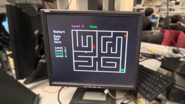
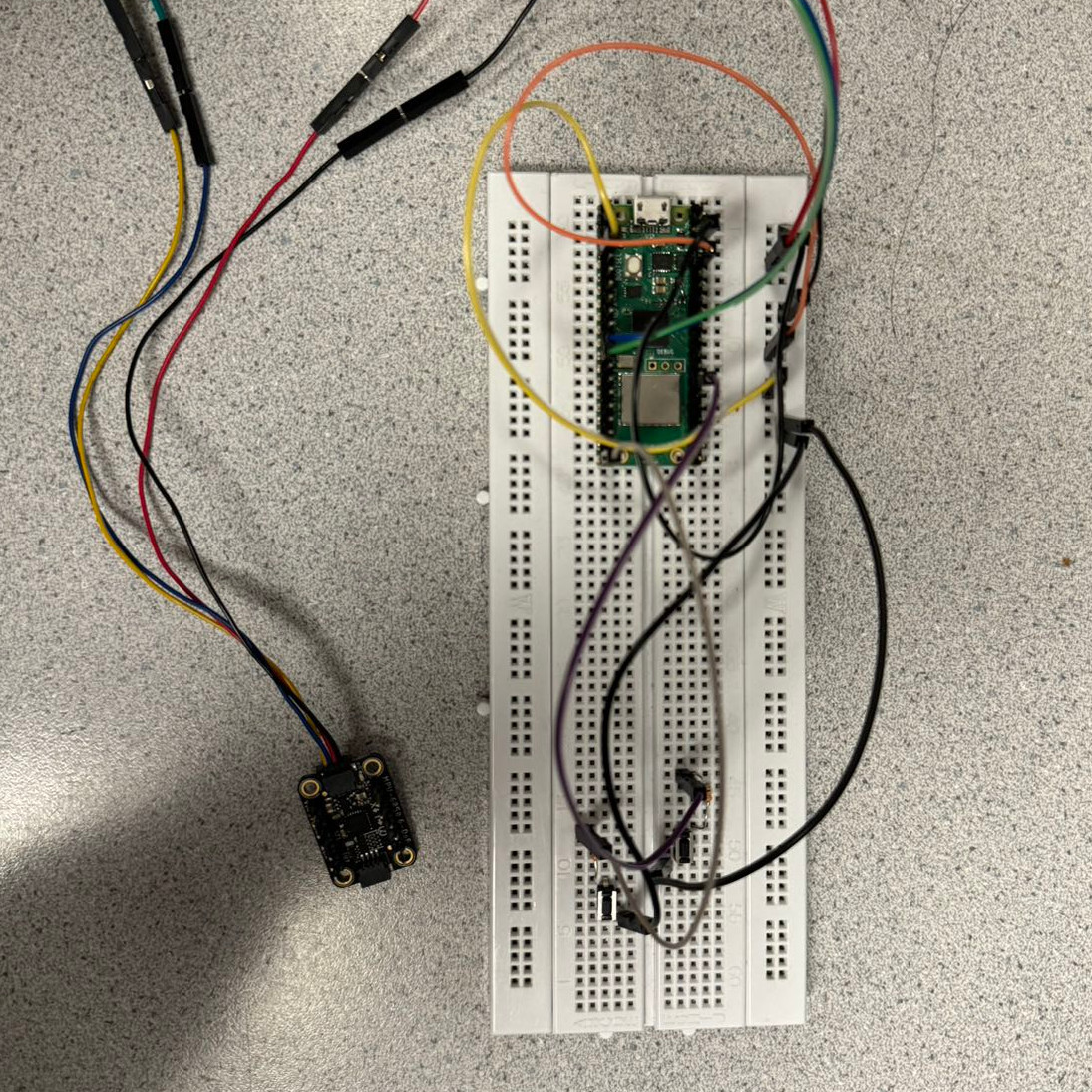 To play, one tilts an MPU6050 inertial measurement unit (IMU) attached to one Pico to guide a square through a 2D maze, with the player working through multiple levels of difficulty. A second Pico takes care of displaying the game state on a VGA monitor, and together they work wirelessly to deliver a coherent experience with the right “feel”. This includes low latency, simulating friction appropriately, and more.
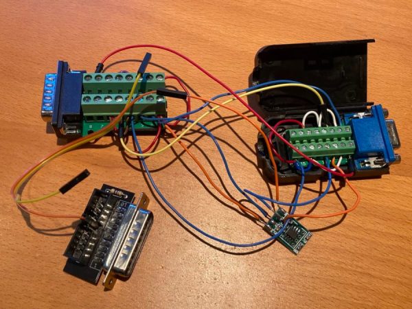
Taking a stream of raw sensor readings and turning them into control instructions over UDP in a way that feels intuitive while at the same time generating a VGA display signal has a lot of moving parts, software-wise. The project write-up has a considerable amount of detail on the architecture of the system, and the source code is available on GitHub for those who want a closer look.
We’ve seen gesture controls interfaced to physical marble mazes before, but two Raspberry Pi Picos doing it wirelessly with a VGA monitor for feedback is pretty neat. Watch it in action in the video, embedded just under the page break.
Continue reading “Gyro-Controlled Labyrinth Game Outputs To VGA”