Reverse Engineering Apple’s Lightning Connector

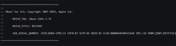
Introduced with the iPhone 5 nearly two and a half years ago, Apple’s Lightning connector has stymied the incredible homebrew electronics scene that was previously accustomed to the larger, older, better documented, and more open 30-pin connector. Now, finally, the protocols inside the Apple Lightning connector have been broken. We’re still a ways off from a Lightning breakout board, but this is the first proof that a serial console can be obtained through a Lightning connector. That’s the first step to totally owning an iDevice, and this is how all those exploits will start.

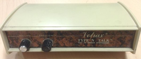
[Ramtin Amin] began the teardown of the Lightning connector began as most reverse engineering tasks should – looking at the patents, finding a source for the connectors, and any other products that use similar hardware. [Ramtin] found a Lightning to Serial converter powered by an STM32 microcontroller. Disassembling the firmware and looking at the output on a logic analyzer, [Ramtin] figured out part of the protocol, most of the wiring, and after some research, schematics for how an until-now unidentified chip in Lightning-enabled iProducts was wired.

The chip in question is colloquially known as the Tristar, and more accurately as a CBTL1608A1. During the teardown craze of the iPhone 5 launch, this chip was frequently identified as a DisplayPort Multiplexer. It is a mux, but not for DisplayPort – it’s only to connect the accessory (Lightning) UART, debug UART, baseband, SoC, and JTAG. This is the key to the castle, and being able to get through this chip means we can now own our iDevices.

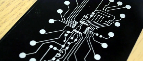
The chip is an incredibly small BGA affair that [Ramtin] desoldered, reflowed onto a breakout board, and connected to an STM32 Discovery board. Using the techniques he used with other Lightning-enabled hardware, [Ramtin] was able to connect his iPhone and ever so slightly peek his head into the inner workings of his device.

It’s not complete control of an iDevice yet, but this is how all those future exploits will start. [Ramtin] uploaded a short video as a proof of concept, you can check that out below.

Continue reading “Reverse Engineering Apple’s Lightning Connector”

1 hour quadcopter build

1-Hour Quadcopter Build

[marhar] was pretty confident in his quadcopter building skills when he made a bet to build and fly a quadcopter in just one hour! This is a big task but he saved valuable time by using some unlikely parts that were hanging around his parts bin. And to make the task a little more difficult, this build wasn’t done in a nice shop, either. It was built outside on a patio floor with the only power tools available being a hand drill, miter saw and small drill press!

The frame is made from cheap, sturdy and available scrap wood. The center plates are 1/4″ plywood and the arms are 3/4″ square fir strips. Notice the landing gear, yes, those are mini wiffle balls zip-tied to the wooden arms. Although an unlikely candidate for landing gear, they are surprisingly effective.

The flight controller board is an Ardupilot. [marhar] did use a flight controller that he previously had in another quadcopter. He used it as-is, and it worked, but no programming or configuration time is included in the 1-hour limit. Even so, it doesn’t take away from the impressiveness of the build time.  The motors, ESC’s and battery are just standard types used for most multirotors.

[marhar] doesn’t say what he won for completing the ‘copter but we hope it was something good, he deserves it. If you’d like to make something similar, [marhar] gives very detailed instructions and provides templates for the wood parts on his Instructables page. Check out the time-lapse build video after the break…

Continue reading “1-Hour Quadcopter Build”

Bill’s Arduino

Pokemon is a great game by itself, but when you realize that not all of the ‘mon are available in one game, trading is required for completion, and some pokemon aren’t available without either hacking or going to a Toys ‘R Us in 1997, you start to see how insidious this game can be. Figuring he could finally complete the game with an Arduino, [Pepijn] decided to build a pokemon storage system.

This build was inspired by an earlier post that also spoofed trades. Instead of building this project around a high-power micro, [Pepijn] decided to use an Arduino. The protocol Game Boys use to communicate with each other is extremely well documented, although that’s only half the battle. Each game using the link cable used specialized data structures for transfer, and after grepping through a disassembled Pokemon ROM,  [Pepijn] figured out how everything worked.

The completed hardware keeps one Pokemon in the EEPROM of an Arduino. It’s not very fast if you want to catch all 151 Pokemon in the Gen 1 games, but any way you look at it, you’re going to be catching a lot of Magikarp anyway.

Wireless Water Level Sensor From PVC Pipe

[Bob] was having trouble keeping up with his water troughs. He had to constantly check them to make sure they weren’t empty, and he always found that the water level was lower than he thought. He decided it was time to build his own solution to this problem. What he ended up with was a water level sensor made from PVC pipe and a few other components.

The physical assembly is pretty simple. The whole structure is made from 1/2″ PVC pipe and fittings and is broken into four nearly identical sensor modules. The sensors have an electrode on either side. The electrodes are made from PVC end caps, sanded down flat at the tip. A hole is then drilled through the cap to accommodate a small machine screw. The screw threads are coated in joint compound before the screw is driven into the hole, creating its own threads. These caps are placed onto small sections of PVC pipe, which in turn connect to a four-way PVC cross connector. 

On the inside of the electrode cap, two washers are placed onto the screw. A stranded wire is placed between the washers and then clamped in place with a nut. All of the modules are connected together with a few inches of pipe. [Bob] measured this out so it would fit appropriately into his trough, but the measurements can easily be altered to fit just about any size container. The wires all route up through the pipe. The PVC pipe is cemented together to keep the water out. The joint compound prevents any leaks at the electrodes.

A piece of CAT 5 cable connects the electrodes to the electronics inside of the waterproof controller box. The electronics are simple. It’s just a simple piece of perfboard with an XBee and a few transistors. The XBee can detect the water level by testing for a closed circuit between the two electrodes of any sensor module. The water acts as a sort of switch that closes the circuit. When the water gets too low, the circuit opens and [Bob] knows that the water level has lowered. The XBee is connected to a directional 2.4GHz antenna to ensure the signal reaches the laptop several acres away. Continue reading “Wireless Water Level Sensor From PVC Pipe”

An Adventure Into Android Makes The VIC-20 Speak

History and [Bil Herd] teaches us that Commodore begged, borrowed, or stole the engineers responsible for the Speak & Spell to add voice synthesis to a few of the computers that came after the C64. This didn’t quite work out in practice, but speech synthesis was something that was part of the Commodore scene for a long time. The Votrax Type ‘n Talk was a stand-alone speech synthesizer that plugged into the expansion port of the VIC-20. It was expensive, rare, but a few games supported it. [Jan] realized the state of speech synthesis has improved tremendously over the last 30 years, and decided to give his VIC a voice with the help of a cheap Android phone.

A few VIC-20 games, including [Scott Adams] adventure games, worked with the Votrax speech synthesizer by sending phonemes as text over the expansion port. From there, the Votrax would take care of assembling everything into something intelligible, requiring no overhead on the VIC-20. [Jan] realized since the VIC is just spitting out characters for each phoneme, he could redirect those words to a better, more modern voice synthesizer.

A small Bluetooth module was wired up to the user port on the VIC, and this module was paired with a cheap Android smartphone. The smartphone receives the serial stream from an adventure game, and speaks the descriptions of all the scenes in these classic adventure games.

It’s a unique experience judging from the video, but the same hardware and software can also be added to any program that will run on the VIC-20, C64, and C128. Video below.

Continue reading “An Adventure Into Android Makes The VIC-20 Speak”

Valentine Heart

Animated LED Valentine Heart

With only a week left until Valentine’s day, [Henry] needed to think on his feet. He wanted to build something for his girlfriend but with limited time, he needed to work with what he had available. After scrounging up some parts and a bit of CAD work, he ended up with a nice animated LED Valentine heart.

[Henry] had a bunch of WS2812 LEDs left over from an older project. These surface mount LED’s are very cool. They come in a small form factor and include red, green, and blue LEDs all in a single package. On top of that, they have a built-in control circuit which makes each LED individually addressable. It’s similar to the LED strips we’ve seen in the past, only now the control circuit is built right into the LED.

Starting with the LEDs, [Henry] decided to build a large animated heart. Being a stickler for details, he worked out the perfect LED placement by beginning his design with three concentric heart shapes. The hearts were plotted in Excel and were then scaled until he ended up with something he liked. This final design showed where to place each LED.

The next step was to design the PCB in Altium Designer. [Henry’s] design is two-sided with large copper planes on either side. He opted to make good use of the extra copper surface by etching a custom design into the back with his girlfriend’s name. He included a space for the ATMega48 chip which would be running the animations. Finally, he sent the design off to a fab house and managed to get it back 48 hours later.

After soldering all of the components in place, [Henry] programmed up a few animations for the LEDs. He also built a custom frame to house the PCB. The frame includes a white screen that diffuses and softens the light from the LEDs. The final product looks great and is sure to win any geek’s heart. Continue reading “Animated LED Valentine Heart”

Ask Hackaday: Are Conductive Inks Going To Make It?

It’s amazing how affordable PCB fabrication has become. It has long been economical (although not always simple) to fabricate your own singe and double-sided boards at home, the access to professional fabrication is becoming universal. The drive continues downward for both cost and turnaround time. But there is growing interest in the non-traditional.

Over the last year we’ve seen a huge push for conductive-ink-based PCB techniques. These target small-run prototyping and utilize metals (usually silver) suspended in fluid (think glue) to draw traces rather than etching the traces out of a single thin layer of copper. Our question: do you think conductive in will become a viable prototyping option?

Voltera V-One Circuit Board Prototyping Machine

I recorded this interview at 2015 CES but was asked not to publish it until their crowd funding campaign went live. If you haven’t been paying attention, Voltera is at almost 400% of their $70k goal with 26 days remaining. This printer definitely works. You can print circuits, solder components or reflow them, and there’s even a second non-conductive ink that can be used to insulate between traces when they cross over one another. In the video [Alroy] suggests Voltera for small production runs of 10-20 boards. Would you see yourself using this for 10-20 boards?

Personally, I think I could solder point-to-point prototypes in less time. Consider this: the V-One will print your traces but you still must solder on the components yourself. If the board design reaches a high level of complexity, that timing may change, but how does the increased resistance of the ink compared to copper traces affect the viability of a board? I assume that something too complex to solder point-to-point would be delving into high-frequency communications (think parallel bus for LCD displays, etc.). Is my assumption correct? Do you think conductive ink will get to the point that this is both viable and desirable over etching your own prototypes and how long before we get there?

Now, I certainly do see some perfect use-cases for Voltera. For instance, introduction to circuit design classes. If you had one of these printers at the middle school or high school level it would jump-start interest in electronics engineering. Without the need for keeping chemical baths like Cuperic Chloride or Ferric Chloride on hand, you could walk students through simple board design and population, with the final product to take home with them. That’s a vision I can definitely get behind and one that I think will unlock the next generation of hardware hackers.

Correction: [Arachnidster] pointed out in the comments that Voltera is still working on being able to reflow boards printed by the V-One. On their Kickstarter page they mention: “(Reflow onto Voltera printed boards is currently under development)”