A Tool For Spying On Serial Data

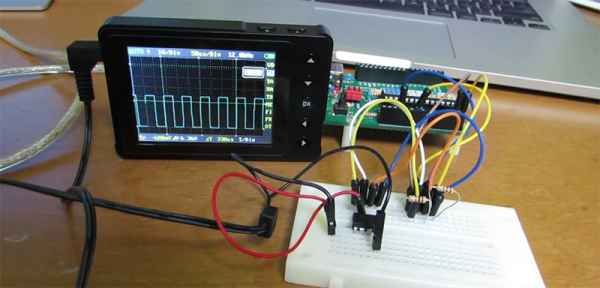
[Piotr] was working on a recent Arduino project when he ran into a problem. He was having trouble getting his Arduino Pro Mini to communicate with an ESP8266 module. He needed a way to snoop on the back and forth serial communications. Since he didn’t have a specialized tool for this task, [Piotr] ended up building his own.

spying-on-serial-thumb
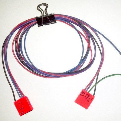
The setup is pretty simple. You start with a standard serial cable containing the TX, RX, DTR, and GND wires. This cable connects the Arduino to the ESP8266 WiFi module. The TX and RX lines are then tapped into. Each wire is routed to the RX pin of two different serial to USB adapters. This way, the data being sent from the Arduino shows up on one COM port and the data being transmitted from the module shows up on the other.

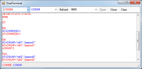
The next piece of the puzzle was coming up with a way to see the data more clearly. [Piotr] could have opened two serial terminals simultaneously, but this wasn’t ideal because it would be difficult to compare the timing of the data. Instead, [Piotr] spent less than an hour writing his own simple serial terminal. This one connects to two COM ports at the same time and prints the data on the same screen. The data from each COM port is displayed in a separate color to make it easy to differentiate. The schematic and source code to this project can be found on [Piotr’s] website.

A Simple Programmable 555

“Instead of an Arduino, he could have done that with a 555 timer.” “Instead of a 555 he could have done that with two transistors.” “Instead of a few transistors, he could have done that with butterflies.” These are quotes from various Hackaday comment threads throughout the years. It seems simplicity is the name of the game here, and if you need a timer chip, how about an 8-pin DIP? This, of course, means an I2C programmable oscillator in the form of an LPC810.

[kodera2t] built this circuit after reaching for a 555 timer a few too many times. It’s a one-chip solution with an ARM core that’s able to generate square waves with 1Hz resolution up to 65536Hz.

The source for this chip is a lot of C, but once it’s in the Flash of the LPC810, this chip becomes a programmable oscillator with an I2C interface. Yes, it’s a one-component solution, no, it’s not a twenty cent chip, but try programming a 555 over I2C.

The videos below show [kodera] playing around with this I2C oscillator, sweeping the frequency from zero to inaudible teenage angst.

Continue reading “A Simple Programmable 555”

slab flattener

Router Jig Makes Quick Work Of Flattening Irregular Shaped Wood

[Nick Offerman] is a pretty serious wood worker. He likes to make crazy stuff including organic looking tables out of huge chunks of wood. Clearly, the wood doesn’t come out of the ground shaped like the above photo, it has to be intensely worked. [Nick] doesn’t have a huge saw or belt sander that can handle these massive blocks of wood so he built something that could. It’s a jig that allows him to use a standard wood router to shave each side down flat.

The process starts by taking a piece of tree trunk and roughing it into shape with a chainsaw. Once it is flat enough to not roll around, it’s put into a large jig with 4 posts. Horizontal beams are clamped to the posts and support a wooden tray which a wood router can slide back and forth in. The router’s cutting bit sticks out the bottom of the tray and slowly nibbles the surface flat. Once one side is flat, the block is rotated and the flat side is used as a reference to make all the other sides square to the first. After flattening, sanding and finishing the block results in a pretty sweet piece of functional artwork.

DIY Tank Tracks Give Tons Of Traction

If you’re building a robot for off-road or rough terrain, chances are you’ve thought about using a tank-tread style drive. There are a ton of kits available with plastic tread and wheels, but they are typically really expensive or pretty flimsy. Instead of going with an off-the-shelf solution, [Paul B] designed a heavy-duty tank tread made with common bike chain and conduit.

Some DIY tread designs we’ve featured just use a single bike chain on either side of the tread pieces. This gets the job done, but each section of tread is usually bolted through the chain. This means that you can’t use a sprocket to drive the chain since all the bolt heads block where the teeth engage. Instead, these designs typically use drive wheels inside the tread, which are prone to slip under a heavy load. [Paul B]’s design is a bit different: it uses a DIY double-wide chain so he can bolt tread segments to the chain and still use a drive sprocket.

Constructing the double-wide chain took quite a bit of work. [Paul B] completely disassembled a couple of bike chains with a delinker tool and then reassembled the chain in a double-wide configuration with M3 bolts instead of the original chain pins. Each section of tread (made out of cut pieces of plastic conduit) bolts on the outside section of chain, and a sprocket runs on the inside. His DIY chain approach saves him money too, since double-wide chains are pretty expensive. Since his sprockets directly engage the drive train, his design should be able to handle as much torque as his drivetrain can put out.

Bitten By PCB Defects

If you’ve ordered PCBs from Seeed Studio, ITead, DirtyPCB, or another board house in China, you’ve probably noticed that neat little 100% e-test option available on the order form. If you select this, the board house will throw your PCBs in a machine that will poke a pin in every pad to make sure all the connections are good. Less work for you, right? As [Andy] found out, not always. He was bitten by a manufacturing defect that sheds some light on what that e-test actually is, and the capabilities of what these Chinese board houses can do.

Most of [Andy]’s project have a lot of surface mount components, and when he receives his boards, he notices a few pin pricks on each and every pad. This is from a flying lead machine; a robotic continuity checker that makes sure all the relevant pads are electrically isolated from each other.

One of [Andy]’s recent projects is an entirely through-hole design. Apparently these robotic meters don’t test through-hole pads; it’s significantly harder to measure the continuity of a hole rather than a pad, apparently. After assembling one of these boards, he noticed a problem where one of the GPIOs was permanently high. The offending trace was found underneath a DIP socket, in precisely the worst possible place it could be.

If [Andy] had inspected the board beforehand, this problem would have been avoided. He says it was a relatively simple board with big traces and wide spaces and he didn’t think a manufacturing defect was possible. He was wrong, and now we have a warning. We thank him for that.

Hackaday Prize Entry: A Better KVM Switch

Now it’s not uncommon to have a desktop and a laptop at a battlestation with tablets waiting in the wings. Add in a few Raspis, consoles, and various cheap computers, and it’s pretty easy to have an enormous number of machines and monitors on a desk. Traditionally, a KVM switch would be the solution to this, sharing a keyboard, mouse, and monitor with many different boxes, but this is an ugly solution. [frankstripod] has a device that fixes that with some interesting software and a few USB hacks.

[frankstripod] is in love with a program called Synergy this program combines the keyboard, mouse, and display of several computers over a network so you’ll only ever have to use one keyboard and mouse; it’s as simple as dragging your mouse from one computer to the other. There are a few limitations, though: keyboards don’t work until the OS has loaded (no BIOS access, then), it doesn’t work if the network is down, and setup can be complicated. This project aims to replace the ‘server’ part of a Synergy setup with a small, networkable KVM.

Right now the plan is to use a small embedded board running Linux to read a USB keyboard and switch the output between several computers. A few scripts detect the mouse moving from one screen to another, and a microcontroller switches USB output between each computer. If it sounds weird, you’re right, but it does work: [frank]’s 2014 Hackaday Prize project was a mouse that worked with two computers at once.


The 2015 Hackaday Prize is sponsored by:

Pinball Simulator Makes The Neighbors Happy

There are a lot of simulators out there if you want to try something out that would be otherwise impossible. Great examples are flight simulators for simulating the piloting of a fighter jet, or goat simulators for simulating the life of a goat who destroys a town. [Erland] wanted a pinball machine, but like planes and goats, found it was impractical to get a real one because it would probably upset his neighbors in his apartment. Instead, he set out to build a pinball simulator.

The cabinet is miniature-sized compared to a regular pinball machine so it can more easily fit in the apartment. It utilizes three monitors, a 24″ one in portrait mode for the main playing area, a 20″ one for the back screen, and a smaller one for the “dot matrix” style scoreboard. Once the woodwork was completed, a PC was put together to control everything and an Arduino was installed to handle the buttons and output USB commands to the PC.

Of course, we’ve featured many other pinball simulators before, but this one is no slouch when it comes to features either. It is very well crafted and the project is very well documented, and the miniature size sets it apart as well. However, if you want to go a step further with your pinball simulator, you might want to check out this augmented reality pinball system.