Solving ISP Problem With A Homebrew LTE Yagi

We’ve heard reports that internet connectivity in Australia can be an iffy proposition, and [deandob] seems to back that up. At the limit of a decent DSL connection and on the fringe of LTE, [deandob] decided to optimize the wireless connection with this homebrew Yagi antenna.

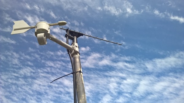
Officially known as the Yagi-Uda after its two Japanese inventors from the 1920s, but generally shortened to the name of its less involved but quicker to patent inventor, the Yagi is an antenna that provides high gain in one direction. That a homebrew antenna was even necessary at all is due to [deandob]’s ISP using the 2300MHz band rather than the more popular 2400MHz – plenty of cheap 2.4GHz antennas out there, but not so much with 2.3GHz. With multiple parallel and precisely sized and spaced parasitic elements, a Yagi can be a complicated design, but luckily for [deandob] the ham radio community has a good selection of Yagi design tools available. His final design uses an aluminum rod for a boom, 2mm steel wire for reflectors and directors, and a length of coax as the driven element. The result? Better connectivity that pushes his ISP throttling limit, and no more need to mount the modem high enough in his house to use the internal antenna.

People on the fringes of internet coverage go to great lengths to get connections, like this off-grid network bridge. Or if you’d rather use a homebrew Yagi to listen to meteors, that’s possible too.

Tiny Matchbox WiFi Weather Station

Sometimes a project doesn’t have to be technically amazing to win over our hearts. [Malte]’s ESP8266-based weather station is so cute, and so nicely executed, that it’s easily worth a look. It could totally be a commercial product, and it’s smaller than a matchbox.

It combines temperature, humidity, and barometric pressure sensors on one side of a PCB, with pads for soldering a pre-built ESP8266 module on the other side. Solder it all together and flash the firmware and you’re almost all set.

The final step is to configure it to work with the network. For this, [Malte] built in a nice web-based configuration (and display) application. It also can log its data to an MQTT system, so there’s a bunch more configuration (which we’re trying to make easier) needed there, and the web frontend makes that light work. Everything, from the hardware to the firmware, and even a pre-compiled binary, is up on his GitHub. Very complete and very well done.

If you can read German, or are willing to run it through a translator, give his personal projects webpage a look as well. Good stuff here. Now all he needs is a matching nice display for inside.

Hackaday Prize Entry: ForEx Display Is A Well Executed Hack

[Stefan] works in a place where knowing the exact state of the foreign-exchange market is important to the money making schemes of the operation. Checking an app or a website was too slow and broke him out of his workflow. OS desktop widgets have more or less departed this earth for the moment. The only solution then, was to build a widget for his actual desk.

The brains of the device is a ESP8266 board, some peripherals and a small backlit TFT display. The device can run off battery or from a wall wart. [Stefan] even added some nice features not typically found in hacks like this, such as a photocell that detects the light level and dims the screen accordingly.

The software uses an interesting approach to get the latest times and timezones. Rather than use a chart or service made for the task, he uses an open weather API to do the task. Pretty clever.

The case is 3D printed and sanded. To get the nice finish shown in the picture [Stefan] spray-painted the case afterwards. All put together the device looks great and gives him the desktop widget he desired.

The HackadayPrize2016 is Sponsored by:

Digitize Your Graphs With WebPlotDigitizer

Have you ever had to write a bit of code to interpret a non-linear analog reading as picked up by an ADC? When all you have to work with for your transfer function is a graph in a semiconductor datasheet that was probably written thirty years ago and prints out the size of a postage stamp, that’s a rather annoying task. Wouldn’t it be nice if you had access to the numbers behind the graph!

You can’t knock on the office door of the engineer who created it back in the ’80s, he’s probably  in retirement and playing golf or growing prize petunias by now. But you can digitize the graph to get yourself a lot closer to the action, and to help you in your quest there’s a handy online tool.

2N3904-current-gain
2N3904 current gain

WebPlotDigitizer is not new, it’s been around for quite a few years now. But it’s still worth talking about, because it’s one of those tools to keep in reserve. If you’ve ever needed it, you’ll know what we mean.

So how does it work? Load an image with a graph in it, select some points on the X and Y axis, roughly trace the curve with a marker tool, and set it in motion. Let’s give it a go. We’re going to try digitizing the current gain plot from the 2N3904 datasheet (PDF) that we examined a few days ago.

data-points
Data points!

So, open the WebPlotDigitizer app, load the graph image captured from the sheet as a JPEG. It asks what type of graph you’ve loaded, in this case a 2D X-Y plot. It asks you to identify four known points on the axes and supply their values. You also tell it if the axes are logarithmic at this point. Select “Automatic mode” on the right hand side, then click “Pen” and mark the graph trace, then select the colour of the trace. Click the “Run” button, and your data points appear. Hit the “View data” button, and there you have it. A few rogue points to remove perhaps, but it does a pretty good job.

If WebPlotDigitizer has engaged your interest, you’ll be pleased to know that it’s open-source, and you can find all its code on GitHub. There is also a handy video tutorial which you can see below the break. Continue reading “Digitize Your Graphs With WebPlotDigitizer”

Reading An IR Thermometer The Hard Way

[Derryn Harvie] from the MakeHackVoid maker space hacked a $10 IR Thermometer and made it talk USB. Sounds easy? Read on.

He opened it up in the hope of finding, and tapping into, a serial bus. But he couldn’t find one, and the main controller was a COB blob – hidden under unmarked black epoxy. Normally this is a dead-end.  (We’ve seen some interesting approaches to decapping epoxy blobs, and even ICs with lasers.)

But [Derryn] went his own way – intercepting the data going from the micro-controller to the LCD display, and reverse engineering it using another microcontroller. He scraped off the solder mask over the tracks leading to the LCD display, and used an oscilloscope to identify the common drive lines. He then used a function generator to excite each of the LCD common lines and the segments lines to build a complete matrix identifying all the combinations that drove the segments. With all the information decoded, wires were soldered so he could hook up an Arduino, and the cut tracks repaired.

Since the LCD was a multiplexed display, the bias voltages were at four levels. Luckily, he could extract most of the LCD information by reading just eight of the segment drive lines, using up all of the analog inputs on the Arduino. Perhaps a different microcontroller with more ADC inputs would have allowed him to display more LCD functions. Well, he can always upgrade his upgrade later. If you have a similar hack to implement, then [Derryn]’s code could be useful to get started.

Thanks, [csirac2] for sending us this tip from MakeHackVoid.

Robo Face Speaks

If you are doing a senior design project in engineering school, it takes some guts to make a robotic duplicate of the school’s president. He or she might be flattered, or completely offended. Us? We laughed out loud. Check out the video below. Spoiler: the nose/moustache wiggle at the end kills us every time.

The project uses a variety of parts including a plastic mask, an Erector set, and the obligatory Arduino with an MP3 shield. There are many articulated parts including eyes, nose, mouth, and wiggly moustache. The face uses RC servos, although [gtoombs] says he’d use stepper motors next time for smoother motion.

Continue reading “Robo Face Speaks”

To See Within: Making Medical X-rays

I was a bit of a lost soul after high school.  I dabbled with electrical engineering for a semester but decided that it wasn’t for me – what I wouldn’t give for a do-over on that one. In my search for a way to make money, I stumbled upon radiologic technology – learning how to take X-rays. I figured it was a good way to combine my interests in medicine, electronics, and photography, so after a two-year course of study I got my Associates Degree, passed my boards, and earned the right to put “R.T.(R) (ARRT)” after my name.

That was about as far as that career went. There are certain realities of being in the health care business, and chief among them is that you really have to like dealing with the patients. I found that I liked the technology much more than the people, so I quickly moved on to bigger and better things. But the love of the technology never went away, so I thought I’d take a look at exactly what it takes to produce medical X-rays, and see how it’s changed from my time in the Radiology Department.

Continue reading “To See Within: Making Medical X-rays”