Hands-On: CCCamp2019 Badge Is A Sensor Playground Not To Be Mistaken For A Watch

Last weekend 5,000 people congregated in a field north of Berlin to camp in a meticulously-organized, hot and dusty wonderland. The optional, yet official, badge for the 2019 Chaos Communication Camp was a bit tardy to proliferate through the masses as the badge team continued assembly while the camp raged around them. But as each badge came to life, the blinkies that blossomed each dusk became even more joyful as thousands strapped on their card10s.

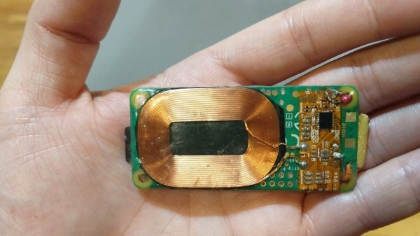
Yet you shouldn’t be fooled, that’s no watch… in fact the timekeeping is a tacked-on afterthought. Sure you wear it on your wrist, but two electrocardiogram (ECG) sensors for monitoring heart health are your first hint at the snoring dragon packed inside this mild-mannered form-factor. The chips in question are the MAX30001 and the MAX86150 (whose primary role is as a pulse sensor but also does ECG). We have high-res ADCs just waiting to be misused and the developers ran with that, reserving some of the extra pins on the USB-C connector for external devices.

There was a 10€ kit on offer that let you solder up some electrode pads (those white circles with gel and a snap for a solid interface with your body’s electrical signals) to a sacrificial USB-C cable. Remember, all an ECG is doing is measuring electrical impulses, and you can choose how to react to them. During the workshop, one of the badge devs placed the pads on his temples and used the card10 badge to sense left/right eye movement. Wicked! But there are a lot more sensors waiting for you on these two little PCBs.

Continue reading “Hands-On: CCCamp2019 Badge Is A Sensor Playground Not To Be Mistaken For A Watch”

Impractical Clock Uses Tuning Fork

Clock projects are so common that they are almost a cliche. After all, microcontrollers have some clock source and are good at counting, so it stands to reason that a clock is an obvious project. [WilkoL’s] clock though has a most unusual clock source: a 440 Hz tuning fork.

A cheap plastic dome really shows off the fork and contributes to this good-looking build. An ATTiny13 divides the input frequency down, handles the display, and obeys the adjustment buttons. It does require a little metalworking, as the tuning fork needed filing and threading, although we bet you could figure out other ways to mount it.

Continue reading “Impractical Clock Uses Tuning Fork”

Pegleg: Raspberry Pi Implanted Below The Skin (Not Coming To A Store Near You)

Earlier this month, a group of biohackers installed two Rasberry Pis in their legs. While that sounds like the bleeding edge, those computers were already v2 of a project called PegLeg. I was fortunate enough to see both versions in the flesh, so to speak. The first version was scarily large — a mainboard donated by a wifi router roughly the size of an Altoids tin. It’s a reminder that the line between technology’s cutting edge and bleeding edge is moving ever onward and this one was firmly on the bleeding edge.

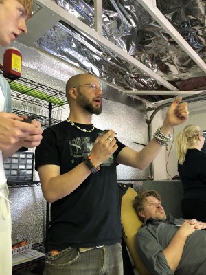
How does that line end up moving? Sometimes it’s just a matter of what intelligent people can accomplish in a long week. Back in May, during a three-day biohacker convention called Grindfest, someone said something along the lines of, “Wouldn’t it be cool if…” Anyone who has spent an hour in a maker space or hacker convention knows how those conversations go. Rather than ending with a laugh, things progressed at a fever pitch.

The router shed all non-vital components. USB ports: ground off. Plastic case: recycled. Battery: repurposed. Amazon’s fastest delivery brought a Qi wireless coil to power the implant from outside the body and the smallest USB stick with 64 GB on the silicon. The only recipient of PegLeg version 1.0 was [Lepht Anonym], who uses the pronoun ‘it’. [Lepht] has a well-earned reputation among biohackers who focus on technological implants who often use the term “grinder,” not to be confused with the dating app or power tool.

Continue reading “Pegleg: Raspberry Pi Implanted Below The Skin (Not Coming To A Store Near You)”

Giant LED Display Is 1200 Balls To The Wall

When you’re going to build something big, it’s often a good idea to start small and work out the bugs first. That’s what [bitluni] did with his massive 1200-pixel LED video wall, which he unveiled at Maker Faire Hanover recently.

We covered his prototype a while back, a mere 300 ping pong ball ensconced-LEDs on a large panel. You may recall his travails with the build, including the questionable choice of sheet steel for the panel and the arm-busting effort needed to drill 300 holes with a hand drill. Not wanting to repeat those mistakes, [bitluni] used the custom hole punch he built rather than a drill, and went with aluminum sheet for the four panels needed. It was still a lot of work, and he had to rig up some help to make the tool more comfortable to use, but in the end the punched holes appear much neater than their drilled counterparts.

[bitluni] mastered enough TIG welding to make nice aluminum frames for the panels, making them lightweight and easy to transport. 1200 ping pong balls, a gunked-up soldering iron, and a package of hot glue sticks later, the wall was ready for electronics. It took a 70-amp power supply and an ESP32 to run everything, but that’s enough horsepower to make some impressive graphics and even stream live video – choppy and low-res, but still usable.

We love the look this wall and we appreciate the effort that went into it. And it’s always good to see just how much fun [bitluni] has with his builds – it’s infectious.

Continue reading “Giant LED Display Is 1200 Balls To The Wall”

Experiments In 3D Graphics Via Excel

3D graphics were once the domain of university research groups and large, specialized computing systems. Eventually, they were tamed and became mainstream. Your phone, tablet, and home computer are all perfectly capable of generating moving 3D graphics. Incidentally, so is Microsoft Excel.

This is the work of of [s0lly], who has been experimenting wtih Excel in this way for quite some time. Starting with pseudo-3D graphics, the project then progressed to the development of a real 3D engine. Naturally, things couldn’t stop there. The next logical step was to advance to raytracing, which was pulled off with aplomb. Shiny spheres on featureless planes are par for the course here.

The graphics are necessarily basic, with resolutions on the order of 256×144. Output is by changing the individual color of the various cells of the spreadsheet. The relevant files are available on Github, for those eager to tinker with experiments of their own. We’ve seen others attempt similar work before, with [C Bel] writing a full game engine for the platform. Video after the break.

Continue reading “Experiments In 3D Graphics Via Excel”

How The Power Gets To The Outlet

[Practical Engineering] is ready to explain how power substations get electricity to you in his latest video, which you can see below.  One of the things we always notice when talking to people either in our community or outside it is that most people have no idea how most of the modern world works.

Ask your non-technical friend to explain how a cell phone works or how a hard drive stores data and you aren’t likely to get a very good answer. However, even most of us are only focused on some particular aspect of electronics. There are a lot of people who hack on robots or radios. The AC power grid,though isn’t something a lot of people work with as a hobby. Do you know exactly what goes on in that substation you pass every day on your commute? If you don’t, you’ll learn something in the video.

Continue reading “How The Power Gets To The Outlet”

FM Signal Detection The Pulse-Counting Way

Compared to the simple diode needed to demodulate AM radio signals, the detector circuits used for FM are slightly more complicated. Wrapping your head around phase detectors, ratio detectors, discriminators, and quadrature detectors can be quite an exercise. There’s another demodulation method that’s not so common, but thankfully it’s also pretty easy to understand: the pulse counting detector.

As [Allan (W2AEW)] notes in the video below, pulse counting is a bit of a misnomer. Pulse counting works by generating a narrow, fixed-width square wave pulse at a set point in the received FM signal’s waveform, usually at the zero-crossing point. Since the frequency of the modulated carrier changes, the duty cycle of the resulting pulse train varies. That means there will be a fixed number of pulses, but by taking the average voltage of the pulse train, we can tease out the original audio frequency signal.

Simple in theory is often more complicated in practice, and [W2AEW] goes into some detail about those complications, such as needing to use a down-converter to make the peak-to-peak frequency deviation in the pulse train more easily detectable. As is his style, he walks us through a test circuit to prove that the theory works in practice. A simple two-transistor circuit generates the pulses at the zero-crossing point, a low-pass filter cleans up the signal, and a cheap audio amplifier reproduces the original audio. It’s a crude circuit to be sure, relying on the stray capacitance of the breadboard to work, but it proves the point and serves as a jumping-off point for further experiments – perhaps using an Arduino to count the pulses?

We always enjoy [W2AEW]’s videos and learn a lot from them. Not long ago we featured another of his videos talking about the mysteries of RF modulation; SSB, anyone?

Continue reading “FM Signal Detection The Pulse-Counting Way”