Motorized Inline Skates Run On Makita Power

Inline skates can be fun, but like most wheeled contraptions, they’re even better when motorized. With just such a goal in mind, [The Real Life Guys] decided to whip up a set of powered skates, running on Makita power!

To get power to the ground, the third wheel on each skate is modified to have a sprocket attached. A Makita drill is then fitted to the skate, transferring power to the wheel through a 90-degree gearbox and a chain drive. The drill is controlled by removing the trigger from the shell and hooking it up with an extended cable.

It’s a lairy setup that probably takes serious practice to use effectively, but does allow for fancy tricks like differential steering if you really want to show off. It’s a great example of using a powerdrill as an all-inclusive motion setup, with the battery, motor and drivetrain already integrated in a neat, tidy package. It’s not the first time we’ve seen a powered set of ‘skates, either! Video after the break.

Continue reading “Motorized Inline Skates Run On Makita Power”

A Strange Display Gives Up Its Secrets

Providing a display for a project in 2020 is something of a done deal. Standard interfaces and off-the-shelf libraries for easily available and cheap modules mean that the hardest choice you’ll have to make about a display will probably relate to its colour. Three decades ago though this was not such a straightforward matter though, and having a display that was in any way complex would in varying proportion take a significant proportion of your processing time , and cost a fortune. [AnubisTTP] has an unusual display from that era, a four-digit LED dot matrix module, and the take of its reverse engineering makes for a fascinating read.

The LITEF 104267 was made in 1986, and is a hybrid circuit in a metal can with four clear windows , one positioned over each LED matrix. Inside are seven un-encapsulated chips alongside the LED matrices on a golf plated hybrid substrate. The chips themselves are not of a particularly high-density process, so some high-resolution photography was able to provide a good guess at their purpose. A set of shift registers drive the columns through buffers, while the rows are brought out to a set of parallel lines. Thus each column can be illuminated sequentially with data presented on the rows. It’s something that would have saved a designer of the day a few extra 74-series chips, though we are guessing at some significant cost.

This display may seem antiquated to us today, but it wasn’t the only option for 1980s designers. There’s one display driver from back then that’s very much still with us today.

A SpaceX Falcon 9 Will Blow Up Very Soon, And That’s OK

They say you can’t make an omelette without breaking a few eggs, and there are few fields where this idiom is better exemplified than rocketry. It’s a forgone conclusion that when you develop a new booster, at least a few test articles are going to be destroyed in the process. In fact, some argue that a program that doesn’t push the hardware to the breaking point is a program that’s not testing aggressively enough.

Which is why, assuming everything goes according to plan, SpaceX will be obliterating one of their Falcon 9 boosters a little after 8:00 AM EST on Saturday morning. The event will be broadcast live via the Internet, and thanks to the roughly 70% propellant load it will be carrying at the moment of its destruction, it should prove to be quite a show.

This might seem like an odd way to spend $62 million, but for SpaceX, it’s worth it to know that the Crew Dragon Launch Abort System (LES) will work under actual flight conditions. The LES has already been successfully tested once, but that was on the ground and from a standstill. It allowed engineers to see how the system would behave should an abort occur while the rocket was still on the pad, but as the loss of the Soyuz MS-10 dramatically demonstrated, astronauts may need to make a timely exit from a rocket that’s already well on the way to space.

In an actual emergency, the crewed spacecraft will very likely be speeding away from a violent explosion and rapidly expanding cloud of shrapnel. The complete destruction of the Falcon 9 that will be carrying the Crew Dragon during Saturday’s test will serve to create the same sort of conditions the spacecraft will need to survive if the LES has any hope of bringing the crew home safely. So even if there was some way to prevent the booster from breaking up during the test, it’s more useful from an engineering standpoint to destroy it.

Of course, that only explains why the Falcon 9 will be destroyed during this test. But exactly how this properly functioning booster will find itself being ripped to pieces high over the Atlantic Ocean in a matter of seconds is an equally interesting question.

Continue reading “A SpaceX Falcon 9 Will Blow Up Very Soon, And That’s OK”

Analyzing CNC Tool Chatter With Audacity

When you’re operating a machine that’s powerful enough to tear a solid metal block to shards, it pays to be attentive to details. The angular momentum of the spindle of a modern CNC machine can be trouble if it gets unleashed the wrong way, which is why generations of machinists have developed an ear for the telltale sign of impending doom: chatter.

To help develop that ear, [Zachary Tong] did a spectral analysis of the sounds of his new CNC machine during its “first chip” outing. The benchtop machine is no slouch – an Avid Pro 2436 with a 3 hp S30C tool-changing spindle. But like any benchtop machine, it lacks the sheer mass needed to reduce vibration, and tool chatter can be a problem.

The analysis begins at about the 5:13 mark in the video below, where [Zach] fed the soundtrack of his video into Audacity. Switching from waveform to spectrogram mode, he was able to identify a strong signal at about 5,000 Hz, corresponding to the spindle coming up to speed. The white noise of the mist cooling system was clearly visible too, as were harmonic vibrations up and down the spectrum. Most interesting, though, was the slight dip in frequency during the cut, indicating loading on the spindle. [Zach] then analyzed the data from the cut in the frequency domain and found the expected spindle harmonics, as well the harmonics from the three flutes on the tool. Mixed in among these were spikes indicating chatter – nothing major, but still enough to measure.

Audacity has turned out to be an incredibly useful tool with a broad range of applications. Whether it be finding bats, dumping ROMs, detecting lightning strikes, or cloning remote controls, Audacity is often the hacker’s tool of choice.

Continue reading “Analyzing CNC Tool Chatter With Audacity”

Car Alternators Make Great Electric Motors; Here’s How

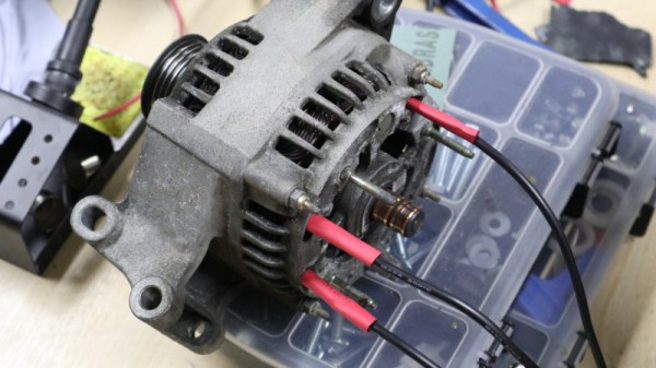
The humble automotive alternator hides an interesting secret. Known as the part that converts power from internal combustion into the electricity needed to run everything else, they can also themselves be used as an electric motor.

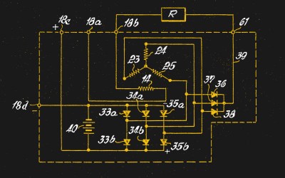
The schematic of a simple automotive alternator, from US patent 3329841A filed in 1963 for Robert Bosch GmbH .
The schematic of a simple automotive alternator, from US patent 3329841A filed in 1963 for Robert Bosch GmbH.

These devices almost always take the form of a 3-phase alternator with the magnetic component supplied by an electromagnet on the rotor, and come with a rectifier and regulator pack to convert the higher AC voltage to 12V for the car electrical systems. Internally they have three connections to the stator coils which appear to be universally wired in a delta configuration, and a pair of connections to a set of brushes supplying the rotor coils through a set of slip rings. They have a surprisingly high capacity, and estimates put their capabilities as motors in the several horsepower. Best of all they are readily available second-hand and also surprisingly cheap, the Ford Focus unit shown here came from an eBay car breaker and cost only £15 (about $20).

We already hear you shouting “Why?!” at your magical internet device as you read this. Let’s jump into that.

Continue reading “Car Alternators Make Great Electric Motors; Here’s How”

Turn By Turn Driving Directions From A Turntable

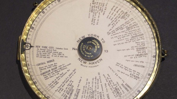
Many of us now carry a phone that can give us detailed directions from where we are to a destination of our choosing. This luxury became commonplace over the last decade plus, replacing the pen-and-paper solution of consulting a map to plan a trip and writing down steps along the way. During the trip we would have to manually keep track of which step we’re on, but wouldn’t it have been nice to have the car do that automatically? [Ars Technica] showed us that innovators were marketing solutions for automatic step by step driving directions in a car over a 100 years ago.

Systems like the Jones Live-Map obviously predated GPS satellites, so they used vehicle odometry. Given a starting point and a mechanical link to the drivetrain, these machines can calculate miles traversed and scroll to the corresponding place in the list of instructions. This is a concept that has been used in many different contexts since, including the “Next Bus in 7 Minutes” type of display at bus stops. Because a bus runs a fixed route, it is possible to determine location of a bus given its odometer reading transmitted over radio. This was useful before the days of cheap GPS receiver and cellular modems. But the odometry systems would go awry if a bus rerouted due to accidents or weather, and obviously the same would apply to those old school systems as well. Taking a detour or, as the article stated, even erratic driving would accumulate errors by the end of the trip.

The other shortcoming is that these systems predated text-to-speech, so reading the fine print on those wheels became a predecessor to today’s distracted driving problem. One of the patent diagrams explained the solution is to hand the device to a passenger to read. But if there’s a copilot available for reading, they can just as easily track the manual list of directions or use a map directly. The limited utility relative to complexity and cost is probably why those systems faded away. But the desire to solve the problem never faded, so every time new technology became available, someone would try again. Just as they did with a tape casette system in the 1970s and the computerized Etak in the 1980s.

[Photo by Seal Cove Auto Museum]

A Behind The Scenes Look At Small Scale Production

Back in 2013, [Karl Lautman] successfully got his kinetic sculpture Primer funded on Kickstarter. As the name implies, you press the big red button on the front of the device, and the mechanical counter at the top will click over to a new prime number for your viewing pleasure. Not exactly a practical gadget, but it does look pretty slick.

These days you can still by your very own Primer from [Karl], but he tells us that the sales aren’t exactly putting food on the table. At this point, he considers it more of a self-financing hobby. To illustrate just what goes into the creation of one of these beauties, he’s put together a time-lapse video of how one gets built from start to finish, which you can see after the break.

Even if you’re not interested in adding a mathematics appliance to your home, we think you’ll agree that the video is a fascinating look at the effort that goes into manufacturing a product that’s only slightly north of a one-off creation.

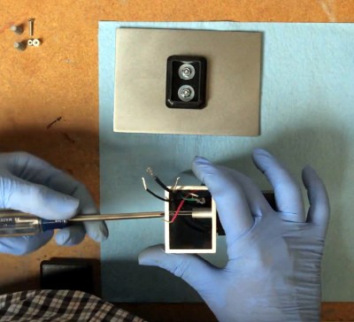
The biggest takeaway is that you really need to be a jack of all trades to pull something like this off. From milling and polishing the metal components to hand-placing the SMD parts and reflowing the board, [Karl] demonstrates the sort of multi-disciplinary mastery you need to have when there’s only one person on the assembly line.

Small scale manufacturing isn’t cheap, and is rarely easy. But stories like this one prove it’s certainly possible if you’re willing to put in the effort.

Continue reading “A Behind The Scenes Look At Small Scale Production”