On the left, an image of a COB on the multimeter's PCB. On the right, a QFP IC soldered to the spot where a COB used to be, with pieces of magnet wire making connections from the QFP's pins to the PCB tracks.

Epoxy Blob Excised Out Of Broken Multimeter, Replaced With A QFP

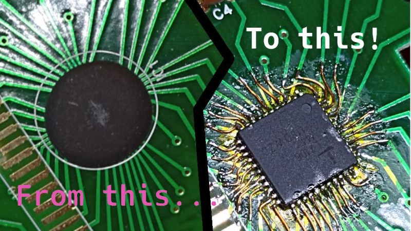
The black blobs on cheap PCBs haunt those of us with a habit of taking things apart when they fail. There’s no part number to look up, no pinout to probe, and if magic smoke is released from the epoxy-buried silicon, the entire PCB is toast. That’s why it matters that [Throbscottle] shared his journey of repairing a vintage multimeter whose epoxy-covered single-chip-multimeter ICL7106 heart developed an internal reference fault. When a multimeter’s internal voltage reference goes, the meter naturally becomes useless. Cheaper multimeters, we bin, but this one arguably was worth reviving.

[Throbscottle] doesn’t just show what he accomplished, he also demonstrates exactly how he went through the process, in a way that we can learn to repeat it if ever needed. Instructions on removing the epoxy coating, isolating IC pins from shorting to newly uncovered tracks, matching pinouts between the COB (Chip On Board, the epoxy-covered silicon) and the QFP packages, carefully attaching wires to the board from the QFP’s legs, then checking the connections – he went out of his way to make the trick of this repair accessible to us. The Instructables UI doesn’t make it obvious, but there’s a large number of high-quality pictures for each step, too.

The multimeter measures once again and is back in [Throbscottle]’s arsenal. He’s got a prolific history of sharing his methods with hackers – as far back as 2011, we’ve covered his guide on reverse-engineering PCBs, a skillset that no doubt made this repair possible. This hack, in turn proves to us that, even when facing the void of an epoxy blob, we have a shot at repairing the thing. If you wonder why these black blobs plague all the cheap devices, here’s an intro.

We thank [electronoob] for sharing this with us!

3D-Printable Sculpture Shows Off Unpredictable Order Of Chains

[davemoneysign] designed this fascinating roller chain kinetic sculpture, which creates tumbling and unpredictable patterns and shapes as long as the handle is turned; a surprisingly organic behavior considering the simplicity and rigidity of the parts.

3D-printed, with a satisfying assembly process.

The inspiration for this came from [Arthur Ganson]’s Machine With Roller Chain sculpture (video, embeded below). The original uses a metal chain and is motor-driven, but [davemoneysign] was inspired to create a desktop and hand-cranked manual version. This new version is entirely 3D-printed, and each of the pieces prints without supports.

According to [davemoneysign], the model works well with a chain of 36 links, but one could easily experiment with more or fewer and see how that changes the results. Perhaps with the addition of a motor this design could be adapted into something like this chains-and-sprockets clock?

You can see [Arthur Ganson]’s original in action in the video embedded below. It demonstrates very well the piece’s chaotic and unpredictable — yet oddly orderly — movement and shapes. Small wonder [davemoneysign] found inspiration in it.

Continue reading “3D-Printable Sculpture Shows Off Unpredictable Order Of Chains”

Adding A Third Wheel (And Speed Boost) To An Electric Scooter

The story of how [Tony]’s three-wheeled electric scooter came to be has a beginning that may sound familiar. One day, he was browsing overseas resellers and came across a new part, followed immediately by a visit from the Good Ideas Fairy. That’s what led him to upgrade his DIY electric scooter to three wheels last year, giving it a nice speed boost in the process!

The part [Tony] ran across was a dual brushless drive unit for motorizing a mountain board. Mountain boards are a type of off-road skateboard, and this unit provided two powered wheels in a single handy package. [Tony] ended up removing the rear wheel from his electric scooter and replacing it with the powered mountain board assembly.

He also made his own Arduino-based interface to the controller that provides separate throttle and braking inputs, because the traditional twist-throttle of a scooter wasn’t really keeping up with what the new (and more powerful) scooter could do. After wiring everything up with a battery, the three-wheeled electric scooter was born. It’s even got headlights!

[Tony]’s no stranger to making his own electric scooters, and the fact that parts are easily available puts this kind of vehicular experimentation into nearly anybody’s hands. So if you’re finding yourself inspired, why not order some stuff, bolt that stuff together, and go for a ride where the only limitation is personal courage?

Animated LED Arrows Point The Way

Visitors at the Garden D’Lights in Bellevue, Washington had a problem. While touring the holiday lights show, they kept straying off the path. The event organizers tried some simple LED arrows, but they were just more points of light among a sea filled with them. This is when [Eric Gunnerson] was asked to help out. He’s apparently had some experience with LED animations, even cooking up a simple descriptor language for writing animations driven by an ESP32. To make the intended path obvious, he turned to a PVC board with 50 embedded WS2812 pixels –RGB controllable LEDs. The control box was a USB power adapter and an ESP8266, very carefully waterproofed and connected to the string of pixels. The backer board is painted black, to complete the hardware. Stick around after the inevitable break, to get a look at the final

The description of the build process is detailed and contains some great tips, but without a clever LED animation, it’s still of questionable utility. The pattern chosen is great, with the LEDs being blue most of the time, and a flame-like gradient chasing through the arrow every couple seconds. It’s obviously different from the lights of the show, and seems to be a real winner. [Eric] has published his code, with the sheepish caveat that he had to reinvent the wheel once again, and couldn’t reuse any of his previous LED animation work on this one. It’s a simple hack, but a great build log, and an effective solution to a subtle problem. And if addressable LEDs are your thing, check out our other hacks!

Continue reading “Animated LED Arrows Point The Way”

CMOS Oscillator Circuit Gets An Eatable Input

In interaction designer [Leonardo Amico]’s work Processing Decay, lettuce is used as an input to produce sound as an element within a CMOS circuit. 

We’ve all seen lemons and potatoes doubling in science-fairs as edible batteries, but lettuce is something else.  [Leandro]’s circuit uses alligator clips to insert lettuce into oscillators in this audio generating circuit — we think they’re behaving like resistors. Without refrigeration, the resistance of the lettuce changes, and so does the oscillation in the circuit. In a matter of hours, days, and weeks the cells degrades slowly, modulating the system and its sonic output. What a way to make music!

This hack isn’t the freshest — the video dates from nine years ago — but this is the first lettuce circuit we’ve seen. Of course, we love other food hacks like these multi-wavelength lasers used to cook 3D-printed chicken, or maybe the circuit can make use of this neural net detecting fruit ripeness. 

Minimal Tic Tac Toe Business Card

The PCB business card has long been a way for the aspiring electronics engineer to set themself apart from their peers. Handing out a card that is also a two player game is a great way to secure a couple minutes of a recruiter’s time, so [Ryan Chan] designed a business card that, in addition to his contact information, also has a complete Tic-Tac-Toe game built in.

[Ryan] decided that an OLED display was too expensive for something to hand out and an LED matrix too thick, so he decided to keep it simple and use an array of 18 LEDs—9 in each of two colors laid out in a familiar 3×3 grid. An ATmega328p running the Arduino bootloader serves as the brains of the operation. To achieve a truly minimal design [Ryan] uses a single SMD pushbutton for control: a short press moves your selection, a longer press finalizes your move, and a several-second press switches the game to a single-player mode, complete with AI.

If you’d like to design a Tic-Tac-Toe business card for yourself, [Ryan] was kind enough to upload the schematics and code for his card. If you’re still pondering what kind of PCB business card best represents you, it’s worth checking out cards with an updatable ePaper display or a tiny Tetris game.

Continue reading “Minimal Tic Tac Toe Business Card”

TRS-80 Gains Multiple Monitor Support, And High-Resolution Graphics

To call [Glen Kleinschmidt] a vintage computing enthusiast would be an understatement. Who else would add the ability to control and address multiple VGA monitors to a rack-mounted TRS-80 Model 1? Multiple 64-color 640×480 monitors might not be considered particularly amazing by today’s standards, but for 70s-era computing, it’s a different story.

Drawing this sin(x)/x ripple surface can be done in only 17 lines of BASIC.

How does a TRS-80 even manage to output anything useful to these monitors? [Glen] wrote his own low-level driver in machine code to handle that. The driver even has useful routines that are callable from within BASIC, meaning that programs written on the TRS-80 are granted powerful drawing abilities. Oh, and did we mention that the VGA graphics cards themselves were designed and made by [Glen]?

Interested in making your own? [Glen] provides all the resources you’ll need to re-create his work, including machine code drivers and demonstration BASIC programs as downloadable audio files, just as they would have been on original cassette tapes.

Watch things in action in the videos embedded below. The first draws a Land Rover, and the second plots a simple Moiré pattern star. Not bad for 70s-era hardware and 74xx logic!

Continue reading “TRS-80 Gains Multiple Monitor Support, And High-Resolution Graphics”