Donkey Kong Bongos Ditch The GameCube, Go Mobile

Historically speaking, optional peripherals for game consoles tend not to be terribly successful. You’ll usually get a handful of games that support the thing, one of which will likely come bundled with it, and then the whole thing fades into obscurity to make way for the next new gimmick.

For example, did you know Nintendo offered a pair of bongos for the GameCube in 2003? They were used almost exclusively by the trio of Donkey Konga rhythm games, although only two of them were ever released outside of Japan. While the games might not have been huge hits, they were successful enough to stick in the memory of [bl3i], who wanted a way to keep the DK bongo experience alive.

The end result is, arguably, more elegant than the hokey musical controller deserves. While most people would have just gutted the plastic bongos and crammed in some new hardware, [bl3i] went through considerable effort so the original hardware would remain intact. His creation simply snaps onto the bongos and connects to them via the original cable.

Internally, the device uses an Arduino to read the output of the bongos (which appeared to the GameCube essentially as a standard controller) and play the appropriate WAV files from an SD card as hits are detected. Add in an audio amplifier module and a battery, and Nintendo’s bongos can finally go forth into the world and spread their beats.

As far as we’re able to tell, this is the first time the Donkey Kong bongos have ever graced the pages of Hackaday in any form, so congratulations to [bl3i] for getting there first. But it’s certainly not the first time we’ve covered ill-conceived game gadgets — long time readers will perhaps be familiar with Nintendo’s attempt to introduce the Robotic Operating Buddy (ROB) to households back in 1985.

Continue reading “Donkey Kong Bongos Ditch The GameCube, Go Mobile”

AI Kayak Controller Lets The Paddle Show The Way

Controlling an e-bike is pretty straightforward. If you want to just let it rip, it’s a no-brainer — or rather, a one-thumber, as a thumb throttle is the way to go. Or, if you’re still looking for a bit of the experience of riding a bike, sensing when the pedals are turning and giving the rider a boost with the motor is a good option.

But what if your e-conveyance is more of the aquatic variety? That’s an interface design problem of a different color, as [Braden Sunwold] has discovered with his DIY e-kayak. We’ve detailed his work on this already, but for a short recap, his goal is to create an electric assist for his inflatable kayak, to give you a boost when you need it without taking away from the experience of kayaking. To that end, he used the motor and propeller from a hydrofoil to provide the needed thrust, while puzzling through the problem of building an unobtrusive yet flexible controller for the motor.

His answer is to mount an inertial measurement unit (IMU) in a waterproof container that can clamp to the kayak paddle. The controller is battery-powered and uses an nRF link to talk to a Raspberry Pi in the kayak’s waterproof electronics box. The sensor also has an LED ring light to provide feedback to the pilot. The controller is set up to support both a manual mode, which just turns on the motor and turns the kayak into a (low) power boat, and an automatic mode, which detects when the pilot is paddling and provides a little thrust in the desired direction of travel.

The video below shows the non-trivial amount of effort [Braden] and his project partner [Jordan] put into making the waterproof enclosure for the controller. The clamp is particularly interesting, especially since it has to keep the sensor properly oriented on the paddle. [Braden] is working on a machine-learning method to analyze paddle motions to discern what the pilot is doing and where the kayak goes. Once he has that model built, it should be time to hit the water and see what this thing can do. We’re eager to see the results.
Continue reading “AI Kayak Controller Lets The Paddle Show The Way”

EMO: Alibaba’s Diffusion Model-Based Talking Portrait Generator

Alibaba’s EMO (or Emote Portrait Alive) framework is a recent entry in a series of attempts to generate a talking head using existing audio (spoken word or vocal audio) and a reference portrait image as inputs. At its core it uses a diffusion model that is trained on 250 hours of video footage and over 150 million images. But unlike previous attempts, it adds what the researchers call a speed controller and a face region controller. These serve to stabilize the generated frames, along with an additional module to stop the diffusion model from outputting frames that feature a result too distinct from the reference image used as input.

In the related paper by [Linrui Tian] and colleagues a number of comparisons are shown between EMO and other frameworks, claiming significant improvements over these. A number of examples of talking and singing heads generated using this framework are provided by the researchers, which gives some idea of what are probably the ‘best case’ outputs. With some examples, like [Leslie Cheung Kwok Wing] singing ‘Unconditional‘ big glitches are obvious and there’s a definite mismatch between the vocal track and facial motions. Despite this, it’s quite impressive, especially with fairly realistic movement of the head including blinking of the eyes.

Meanwhile some seem extremely impressed, such as in a recent video by [Matthew Berman] on EMO where he states that Alibaba releasing this framework to the public might be ‘too dangerous’. The level-headed folks over at PetaPixel however also note the obvious visual imperfections that are a dead give-away for this kind of generative technology. Much like other diffusion model-based generators, it would seem that EMO is still very much stuck in the uncanny valley, with no clear path to becoming a real human yet.

Continue reading “EMO: Alibaba’s Diffusion Model-Based Talking Portrait Generator”

Bidirectional Data Transfer Through Mud?

We take easy communications for granted these days. It’s no bother to turn on a lightbulb remotely via a radio link or sense the water level in your petunias, but how does a drilling rig sense data from the drill head whilst deep underground, below the sea bed? The answer is with mud pulse telemetry, about which a group of researchers have produced a study, specifically about modelling the signal impairments and strategies for maintaining the data rate and improving the signal quality.

If you’re still confused, mud pulse telemetry (MPT) works by sending a modulated pressure wave vertically through the column of mud inside the drilling tube. It’s essential to obtain real-time data during drilling operations on the exact angle and direction the drill bit is pointing (so it can be corrected) and details of geological formations so decisions can be made promptly. The goal is to reduce drilling time and, therefore, costs and minimize environmental impact — although some would strongly argue about that last point.

Continue reading “Bidirectional Data Transfer Through Mud?”

A business card-sized love detector in a 3D-printed package.

2024 Business Card Challenge: Who Do You Love?

When you hand your new acquaintance one of your cards, there’s a chance you might feel an instant connection. But what if you could know almost instantly whether they felt the same way? With the Dr. Love card, you can erase all doubt.

As you may have guessed, the card uses Galvanic Skin Response. That’s the fancy term for the fact that your skin’s electrical properties change when you sweat, making it easier for electricity to pass through it. There are two sensors, one on each short end of the card where you would both naturally touch it upon exchange. Except this time, if you want to test the waters, you’ll have to wait 10-15 seconds while Dr. Love assesses your chemistry.

The doctor in this case is an RP2040-LCD-0.96, which is what it sounds like — a Raspberry Pi Pico with a small LCD attached. For the sensors, [Un Kyu Lee] simply used 8mm-wide strips of nickel. If you want to build your own, be sure to check out the build guide and watch the video after the break for a demonstration of Dr. Love in action.

Continue reading “2024 Business Card Challenge: Who Do You Love?”

Switching Regulator Layout For Dummies

Last time, we went over switching regulator basics – why they’re wonderful, how do you find a switching regulator chip for your purpose, and how to easily pick an inductor for one. Your datasheet should also tell you about layout requirements. However, it might not, or you might want to deviate from them – let’s go more in-depth on what those requirements are about.

Appreciate The Feedback

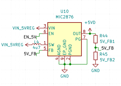
The two resistors on the right decide what your output voltage will be, and their output is noise-sensitive

There’s a few different switching regulator topologies. Depending on your regulator’s topology and how many components your chip contains, you might need some external components – maybe a Schottky diode, maybe a FET, or maybe even a FET pair. It’s often that the FET is built-in, and same goes for diodes, but with higher-current regulator (2 A to 3 A and above), it’s not uncommon to require an external one. For sizing up those, you’ll want to refer to the datasheet or existing boards.

Another thing is input and output capacitors – don’t skimp on those, because some regulators are seriously sensitive to the amount of capacitance they’re operating with. Furthermore, if you fail to consider things like capacitance dropping with voltage, you might make your regulator very unhappy – not that a linear regulator would be happy either, to be clear. We’ve covered an explainer on this recently – do check it out!

One thing you will likely need, is a feedback resistor divider – unless your switching regulator is pre-set for a certain voltage or is digitally controlled, you need to somehow point it to the right voltage, in an analog way. Quite a few switching regulators are set for a certain voltage output, but most of them aren’t, and they will want you to add a resistor divider to know what to output. There’s usually a formula for resistor divider calculation, so, pick a common resistor value, put it in as one of the resistors into the formula, get the other resistor value out of that formula, and see what’s the closest value you can actually buy. Don’t go below about 10 kΩ so that you don’t have unnecessary idle power consumption, but also don’t go too far above 100 kΩ to ensure good stability of the circuit. Continue reading “Switching Regulator Layout For Dummies”

A Peek Inside Apple Durability Testing Labs

Apple is well-known for its secrecy, which is understandable given the high stakes in the high-end mobile phone industry. It’s interesting to get a glimpse inside its durability labs and see the equipment and processes it uses to support its IP68 ingress claims, determine drop ability, and perform accelerated wear and tear testing.

Check out these cool custom-built machines on display! They verify designs against a sliding scale of water ingress tests. At the bottom end is IPx4 for a light shower, but basically no pressure. Next up is IPx5, which covers low-pressure ambient-temperature spray jets from all angles – we really liked this machine! Finally, the top-end IPx7 and IPx8 are tested with a literal fire hose blast and a dip in a static pressure tank, simulating a significant depth of water. An Epson robot arm with a custom gripper is programmed to perform a spinning drop onto a hard surface in a repeatable manner. The drop surface is swapped out for each run – anything from a wooden sheet to a slab of asphalt can be tried. High-speed cameras record the motion in enough detail to resolve the vibrations of the titanium shell upon impact!

Accelerated wear and tear testing is carried out using a shake table, which can be adjusted to match the specific frequencies of a car engine or a subway train. Additionally, there’s an interview with the head of Apple’s hardware division discussing the tradeoffs between repairability and durability. He makes some good points that suggest if modern phones are more reliable and have fewer failures, then durability can be prioritized in the design, as long as the battery can still be replaced.

The repairability debate has been raging strong for many years now. Here’s our guide to the responsible use of new technology.

Continue reading “A Peek Inside Apple Durability Testing Labs”