Quadruped Robot Thinks It’s A Puppy

puppybot
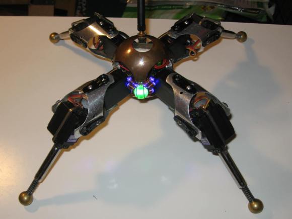
Back at New York MakerFaire 2012, we noticed an amazing little steampunk quadruped robot walking around in the crowd outdoors. The robot was amazingly well executed, and had a unique ability to draw children over with it’s puppy like animations. It turns out this is [Drew’s] Little Walking Robot (AKA Puppy Bot).

Puppy Bot has actually been around for quite a while. He was born from the spare parts [Drew] had left over after competing in Robot Wars and Battlebots. The robots in these competitions were often controlled by Radio Control plane or car transmitters. Most of these systems are sold as packs for an RC car or plane. In addition to the transmitter and receiver, the pack usually included a battery and 3 or 4 servos. Standard RC servos were much too weak for use in battle robots, so they remained in his parts box.

On what [Drew] calls a slow weekend, he started putting the servos together, and ended up with a basic robot that could crawl around the room. After that the robot took on a life of its own. [Drew] improved the battery system, and added a microcontroller to automate the various gaits and animations. He brought the robot along with him to one of his battlebot competitions, and it took home the “Coolest Robot” award – even though it wasn’t actually competing!

Continue reading “Quadruped Robot Thinks It’s A Puppy”

Monitor GitHub Activity With An RGB LED Matrix

tim-display

Ever wonder who is forking your code? [Jack] did, so he built a real time GitHub activity display for his company’s repositories. The display is based a Wyolum The Intelligent Matrix (TiM) board. The TiM is an 8 x 16 matrix of the ubiquitous WS2811/Smart Pixel/NeoPixel RGB LEDs with built-in controller. We’re seeing more and more of these serial LEDs as they drop in price. Solder jumpers allow the TiM to be used as 8 parallel rows of LEDs (for higher refresh rates), or connected into one long serial chain.

[Jack] wasn’t worried about speed, so he configured his board into a single serial string of LEDs. An Arduino drives the entire matrix with a single pin. Rather than reinvent the wheel, [Jack] used Adafruit’s NeoMatrix library to drive his display. Since the TiM uses the same LEDs as the Adafruit NeoPixel Matrix, the library will work. Chalk up another victory for open source hardware and software!

An Electric Imp retrieves Github data via WiFi and passes it on to the Arduino. This is a good use of a microcontroller such as the AVR on the Arduino. [Jack’s] display has a scrolling username. Every step in the scroll animation requires all the pixel data be clocked out to the TiM board. The Arduino can handle this while the IMP takes care of higher level duties.

Continue reading “Monitor GitHub Activity With An RGB LED Matrix”

Teach An Old LCD New Tricks

pic-lcd

[Art] has done some amazing work with character LCDs. He started with a classic character LCD. These LCDs are typically controlled by Hitachi HD447XXX compatible controllers. Hitachi’s controllers allow several custom characters to be defined. We’ve used those characters in the past for applications like spinners and bar graphs. [Art] took things to a whole new level. He created a double buffered LCD graphics library which allows these old LCDs to perform tricks usually reserved for graphical LCDs. Even more impressive is the fact the whole thing runs on a Microchip PIC16F628A programmed mostly in PICBASIC.

According to [Art’s] thread on the PICBASIC forum, he is using the custom character memory as a framebuffer. The LCD is set to display all 8 custom characters. Each frame is then in the PIC’s RAM. The completed frames are then pushed to the custom character memory of the Hitachi LCD controller. The result is a very smooth update rate on the LCD. [Art] wrapped the whole example up in a video reminiscent of the C64 demoscene.

Continue reading “Teach An Old LCD New Tricks”

VT100 Gets BeagleBoned

vt100

How do you make a great terminal even better?  The answer is simple: add a BeagleBone Black to it! [Brendan] got his hands on one of the staples of classic computing, the DEC VT100 terminal.  The VT100 was produced from 1978 to 1983. The terminal was so widely used that it became the standard for other terminals to emulate. Open any terminal program today and chances are you’ll find a setting for VT100 emulation.

[Brendan] originally hooked his terminal up to a laptop running Linux. The terminal, cables, and the laptop itself became quite a bit to manage on a small desk. To combat this he decided to add a BeagleBone Black inside the terminal case. It turns out the VT100 actually lends itself to this with its Standard Terminal Port (STP) connector. The STP was designed to add a “paddle board” in-line with the serial stream of the terminal. DEC and third party manufacturers used this port to add everything from disk drives to entire CPM computers to the VT100.

[Brendan] began by designing a board to interface between the VT100 and the BeagleBone. The board level shifts serial lines from the BeagleBone to the VT100. The STP also allows the terminal to provide power to the BeagleBone Black.  He did notice some power glitches as the supply of the VT100 came up. This was solved with a standard TI TL77xx voltage supervisor chip. The hardest part of the entire design was the card edge connector for the STP. [Brendan] nailed the dimensions on the first try.  In the end [Brendan] was rewarded with a very clean installation that didn’t require any modification to a classic piece of hardware.

We should note that most PCB houses use Electroless Nickel Immersion Gold (ENIG) as their standard coating. This will work for a card edge connector that will be plugged in and removed a few times.  Cards that will be inserted and removed often (such as classic console cartridges) will quickly scrape the ENIG coating off. Electroplated Gold over Nickel is the classically accepted material for card edge connectors, however the process most likely is not going to come cheap in hobbyist quantities.

CastAR Goes Live On Kickstarter

castar2
[Jeri, Rick and the Technical Illusions crew] have taken the castAR to Kickstarter. We’ve covered castAR a couple of times in the past, but the Kickstarter includes a few new features just ripe for the hacking. First, castAR is no longer confined to a retro-reflective surface. In fact, it’s no longer confined to augmented reality. An optional clip on adapter converts castAR into a “free” augmented reality or a full virtual reality system.

[Jeri] has also posted a video on her YouTube channel detailing the entire saga of castAR’s development (embedded after the jump). The video has a real “heart to heart” feel to it, and is definitely worth watching. The story starts with the early days (and late nights) [Rick] and [Jeri] spent at Valve. She goes through the split with Valve and how the two set up a lab in [Rick’s] living room. [Jeri] also outlines some of the technical aspects of the system. She explains how the optics have been reduced from several pounds of projectors to the mere ounces we see today.

Another surprise addition is the lower level tier rewards of the campaign. The castAR tracking system is offered. The campaign page says the tracking system can be mounted to anything from robots to other VR headsets. The possibilities for hacking are almost endless. We’re curious about setting up our own swarm of quadcopters similar to the UPENN Grasp Lab. The RFID tracking grid is also offered as a separate option. In the gaming system this will be used for tracking tabletop game pieces. Based upon the Kickstarter page, it sounds as if the grid will not only use RFID, but a camera based tracking system. We’re definitely curious what possibilities this will hold.

As of this writing, the castAR Kickstarter campaign is already well past the halfway mark on its way to a $400,000 USD goal.

Continue reading “CastAR Goes Live On Kickstarter”

Build A DIY Plate Reverb

PlateReverb

[Telegraphy] needed a reverb for his recording studio. There are hundreds of computer-based and standalone digital reverb systems out there, but he decided to build his own plate reverb. Reverb is an effect used in many professional audio and music recordings. Reverb adds thousands of echos to an audio signal. These echos decrease in amplitude over time. When used correctly, the effect is generally very pleasing to the ear.

A plate reverb uses a plate of sheet metal to generate the reverb. An audio driver is placed in contact with the metal plate. Audio is fed into the driver, which vibrates the plate. The vibrations travel along the surface of the plate, bouncing off the edges and reflecting back. These reflections are captured by a pickup, which then converts them to a voltage signal. The final reverb effect is actually created in the sound engineer’s mixing board when the “dry” source signal is mixed with the signal returned by the plate.

[Telegraphy’s] plate reverb was built almost entirely from found, Radio Shack, and hardware store parts. The plate and frame are from Lowes. The audio driver is a cut up speaker from an old car stereo. The pickup is a modified piezo transducer from Radio Shack. As [Telegraphy] states several times, there are a lot of differing opinions on exactly how and where to mount the various parts of the reverb. Any placement will generate some reverb. The question is where and how to mount things for the best effect. Much like beauty and the eye of the beholder, the answer to that question is in the ear of the listener.

Jump past the break for a tour of a slightly more involved plate reverb at Gallery Acoustics Studio.

Continue reading “Build A DIY Plate Reverb”

Turbot Is A Beam/Picaxe Hybrid

[James] wanted to build a BEAM turbot. He ran into some problems with the BEAM circuitry though, and ended up with a BEAM/Picaxe hybrid.
Beam robotics
are the brainchild of Mark Tilden. The acronym stands for Biology, Electronics, Aesthetics, and Mechanics. BEAM based bots were very popular with hobbyists in the 90’s and early 2000’s, but popularity has since died down. BEAM robots tend not to use microcontrollers, instead attempting to simplify things down to the lowest number of elements.

[James’] turbot uses a miller solar engine. The original design used the engine to drive a Solar Turbot Latch. [James’] problem was that the photodiode “eyes” of the robot were not properly enabling the 74AC245 to pass current to the motor. Since the robot was built in a tiny space, debugging the circuit was extremely hard. After struggling with the ‘245 for some time, [James] decided to swich out the BEAM circuit for a Picaxe microcontroller.

The Picaxe can only sink or source about 20ma per pin, which is slightly less than the no load current of [James’] motors. To make up for this, he ganged up four pins per motor. There was some risk in the motors blowing up the Picaxe. However between the lightly loaded gearmotors and low current solar panels it seems to be working just fine.  Overall the bot is a very clean, compact build. Jump past the break to check out its really smooth crablike walking action.

Continue reading “Turbot Is A Beam/Picaxe Hybrid”