
Ever wanted to see how well your oscilloscope adheres to its stated capabilities? What if you buy a new scope and need a quick way to test it lest one of its channels its broken, like [Paul Wasserman] had happen to him? Now you only need a Pi Pico and a few extra components to make a scope test board with a large variety of signals it can output, thanks to [Paul]’s Sig Gen Pi Pico firmware.
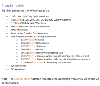 Despite the name it’s not a signal generator as we know it, as it’s not flexible in the signals it generates. Instead, it creates a dozen signals at more or less the same time — from square waves of various frequencies and duty cycles, to a PWM-driven DAC driving eight different waveforms, to Manchester-encoded data I2C/SPI/UART transfers for all your protocol decoder testing.
Everything is open source under the BSD 3-Clause license, and there’s even two PDFs with documentation and a user manual, not to mention the waveform screenshots for your own reference.
It’s seriously impressive how many features [Paul] has fit into a single firmware. Thanks to his work, whenever you have some test equipment in need of being tested, just grab your Pico and a few passive components.


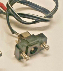 This board’s idea is thought-out and executed well – it replaces a bespoke barrel jack assembly, and is mechanically designed to fit the screw holes and the free space inside the chassis. For USB-PD, it uses a CH32V003 coupled with FUSB302 – I definitely
![The film scanner [xssfox] found, in the center of a table, with other stuff strewn across the table](https://hackaday.com/wp-content/uploads/2024/05/hadimg_iscsi_scanner_feat.png?w=600&h=450)


