A Staple Gun, Caulking Gun, And Four-Barrel Shotgun

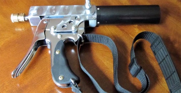
In its native form, [Clint]’s K-441 is a caulking gun, able to apply silicones, resins, and liquid rubber from a reservoir with compressed air. It’s accurate, powerful, has a huge capacity, and looks strangely steampunk, even for caulking gun standards. This isn’t any normal caulking gun; this device was made from a staple gun. Oh, it also fires shotgun shells with the help of four rifled barrels.

This device that shoots lead, steel, and glue started off its life as an ordinary staple gun, with the usual 23lb pull you’ll find on these guns. By adding a few plates, hand-winding a spring, and milling a few parts, [Clint Westwood] turned this staple gun into a device that would shoot a single .410 bore shell. A practice round as far as shotguns go, but still a serious amount of punch.

Continue reading “A Staple Gun, Caulking Gun, And Four-Barrel Shotgun”

Micro Word Clock

A word clock – a clock that tells time with words, not dials or numbers – is one of those builds that’s on every Arduino neophyte’s ‘To Build’ list. It’s a bit more complex than blinking a LED, but an easily attainable goal that’s really only listening to a real time clock and turning a few LEDs on and off in the right pattern.

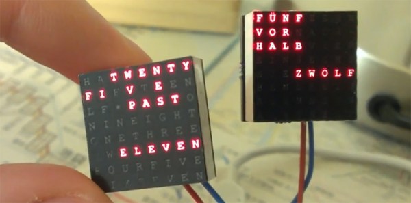
One of the biggest hurdles facing anyone building a word clock is the construction of the LED matrix; each LED or word needs to be in its own light-proof box. There is another option, and it’s something we’ve never seen before: you can just buy 8×8 LED matrices, so why not make a word clock out of that? That’s what [Daniel] did, and the finished project is just crying out to be made into a word watch.

[Daniel]’s word clock only uses eight discrete components: an ATMega328p, a DS1307 real time clock, some passives, and an 8×8 LED matrix. A transparency sheet with printed letters fits over the LED matrix forming the words, and the entire device isn’t much thicker than the LED matrix itself.

All the files to replicate this build can be found on [Daniel]’s webpage, with links to the Arduino code, the EAGLE board files, and link to buy the board on OSH Park.

[Fran]’s New Project: The DSKY

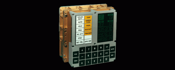
[Fran] has already made a name for herself in some retro cool historical aviation and computer circles by tearing down a flight-ready spare of a Saturn V launch vehicle digital computer, the computer that was responsible for getting all flights to the moon into low earth orbit. Now she’s ready for another project, and again, this is something that hasn’t been done in 40 years. She’s building a DSKY, the control panel for the Apollo Guidance Computer

The Apollo Guidance Computer is a well-documented piece of computing history, with homebrew versions all over the web. The DSKY is only one small part of the AGC, but it is by far the most famous module. Being the only user interface for the AGC, it’s the only part of the AGC that gets all the screen time in Apollo 13, the travesty on BluRay that was Apollo 18, and is the only device that bears any physical resemblance to its real-life counterpart in a number of AGC simulators.

That’s not to say DSKY builds haven’t been attempted before; there are a few out there using LEDs and off-the-shelf buttons for the build, but the DSKY from the mid-60s is much, much cooler than a bunch of LEDs and light pipes. The eery green numbers are actually EL displays. Guess how those displays are controlled? Relays. It’s a masterpiece of technology, made even more impressive in that the folks at MIT who built the thing didn’t have anything better to build the display with.

Because of her deconstruction efforts with the Saturn V LVDC, [Fran] was invited down to the National Air and Space museum in the middle of Washington DC. There, she saw everyones favorite ugliest spacecraft, the Apollo LEM, along with an incredible assortment of paraphernalia from aviation history. The Wright Flyer – yes, the original one – is hanging from the ceiling next to the Spirit of St. Louis, and X-15 rocket plane, right above the command module Columbia from Apollo 11. Copies of probes currently rolling over Mars are on display, and you can walk through a training model of Skylab. If you’ve never been, spend half a day there, then take the metro out to the Udvar-Hazy center, where you’ll find all the stuff they couldn’t fit in the downtown collection like a Space Shuttle and a Concorde.

This is only the first part of [Fran]’s vlog documenting the construction of a copy of the DSKY, and we haven’t even seen the inner guts of the most famous part of the AGC yet. She’s been working on this for a while now, and there’s no doubt she’ll finish the job and come up with the best replica of a DSKY ever.

Adding A Steady Rest To A Lathe

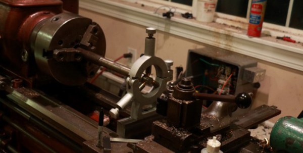
A steady rest is a tool for a lathe, enabling a machinist to make deep cuts in long, slender stock, bore out thin pieces of metal, and generally keeps thin stuff straight. Unlike a tool that follows the cutter, a steady rest is firmly attached to the bed of a lathe. [Josh]’s lathe didn’t come with a steady rest, and he can’t just get parts for it. No problem, then: he already has a lathe, mill, and some metal, so why not make the base for one from scratch?

[Josh] was able to find the actual steady rest from an online dealer, but it wasn’t made for his lathe. This presented a problem when attaching it to his machine: because each steady rest must fit into the bed of the lathe, he would need a custom bracket. With the help of a rather large mill, [Josh] faced off all the sides of a piece of steel and cut a 45 degree groove. To make this base level, [Josh] put one side of the base on the lathe, put a dial micrometer on the tool post, and got an accurate reading of how much metal to take off the uncut side.

With the steady rest bolted onto the lathe, [Josh] turned a rod and found he was off by about 0.002″. To machinists, that’s not great, but for a quick project it’s fantastic. Either way, [Josh] really needed a steady rest, and if it works, you really can’t complain.

Continue reading “Adding A Steady Rest To A Lathe”

Analog Instagram

Several decades ago, the all the punks and artsy types had terrible lenses with terrible camera that leaked light everywhere. Film was crap, and thus was born the fascinating world of Lomography, with effects and light leaks unique to individual cameras. Now, everyone has a smartphone with high-resolution sensors, great lenses, and Instagram to replicate the warm look of filters, light leaks, and other ‘artististic’ photographic techniques. The new version of this photography is purely in the digital domain, and wouldn’t it be great if there was a way to make your digital selfies analog once again? The SnapJet team has your back.

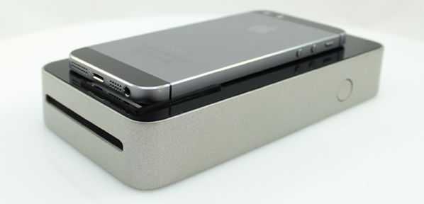
Instead of adding filters and other digital modifications to smartphone snaps, the SnapJet prints pictures onto Polaroid film. Yes, you can still buy this film, and yes, it’s exactly how you remember it. By putting a smartphone down on the SnapJet, you’ll only need to press a button, wait for the film to be exposed, dispensed, and developed. What comes out of the SnapJet is an analog reproduction of whatever is displayed on your phone’s screen, with all the digital filters you can imagine and the option to modify the photos in the analog domain; eac Polaroid can be turned into a transparency, with backlit LEDs being an obvious application:

gif

Continue reading “Analog Instagram”

Improving The T-962 Reflow Oven

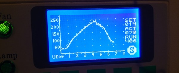
The T-962A is a very popular reflow oven available through the usual kinda-shady retail channels. It’s pretty cheap, and therefore popular, and the construction actually isn’t abysmal. The controller for this oven is downright terrible, and [wj] has been working on a replacement firmware for the horribly broken one provided with this oven. It’s open source, and the only thing you need to update your oven is a TTL/UART interface.

[WJ] bought his T-962A even after seeing some of the negative reviews that suggested replacing the existing controller and display. This is not in true hacker fashion – there’s already a microcontroller and display on the board.

The new firmware uses the existing hardware and adds a very necessary modification: stock, the oven makes the assumption that the cold-junction of the thermocouples is at 20°C. The controller sits on top of an oven with two TRIACs nearby, so this isn’t the case, making the temperature calibration of the oven slightly terrible.

After poking around the board, [WJ] found an LPC2000-series microcontroller and a spare GPIO pin for a 1-wire temperature sensor. The temperature sensor is placed right next to the terminal block for the thermocouples for proper temperature sensing.

All the details of updating the firmware appear on a wiki, and the only thing required to update the firmware is a serial/USB/UART converter. A much better solution than ripping out the controller and replacing it with a custom one.

HDMI Out With A Brick Game Boy

A few years ago, some vastly clever people figured out how to listen in on the LCD display on the classic brick Game Boy from 1989. There have been marked improvements over the years, including a few people developing VGA out for the classic Game Boy. Now, the bar has been raised with an HDMI adapter for the Game Boy, designed in such a way that turns everyone’s favorite battery hog into a portable console.

Your classic beige or cleverly named Color Game Boy is composed of two halves. The rear half contains all the important circuitry – the CPU, cartridge connector, and the rest of the smarts that make the Game Boy game. The front half is fairly simple in comparison, just an LCD and a few buttons. By designing an adapter that goes between these two halves, [Zane] and [Joshua] were able to stuff enough circuitry inside the Game Boy to convert the signals going to the LCD to HDMI. Plug that into your TV, and you have a huge modern version of the Super Game Boy, no SNES required.

The HDMIBoy also breaks out the buttons to the classic NES controller connector. With HDMI out and a controller input, the old-school Game Boy become a portable if somehow even more brick-like console.