Many people have been attracted to the low price and big dreams of the CNC3018 desktop CNC router. If you’re quick, you can pick one up on the usual second-hand sales sites with little wear and tear for a steal. They’re not perfect machines by any stretch of the imagination, but they can be improved upon, and undoubtedly useful so long as you keep your expectations realistic.
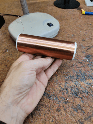
[ForOurGood] has set about such an improvement process and documented their journey in a whopping eight-part (so far!) video series. The video linked below is the most recent in the series and is dedicated to creating a brushless spindle motor on a budget.
As you would expect from such a machine, you get exactly what you pay for. The low cost translates to thinner than ideal metal plates, aluminium where steel would be better, lower-duty linear rails, and wimpy lead screws. The spindle also suffers from cost-cutting, as does the size of the stepper motors. But for the price, all is forgiven. The fact that they can even turn a profit on these machines shows the manufacturing prowess of the Chinese factories.
We covered the CNC 3018 a while back, and the comments of that post are a true gold mine for those wanting to try desktop CNC. Warning, though: It’s a fair bit harder to master than 3D printing!