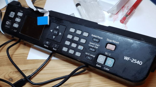
[Thane Hunt] needed to find a way to make a variety of different heat-seal patterns on a fluid heat exchanger made from polyolefin film, and didn’t want all the lead time and expense of a traditional sealing press machined from a steel plate. Pattern prototyping meant that the usual approach would not allow sufficient iteration speed and decided to take a CNC approach. Now, who can think of a common tool, capable of positioning in the X-Y plane, with a drivable Z axis and a controlled heat source? Of course, nowadays the answer is the common-or-garden FDM 3D printer. As luck would have it, [Thane] had an older machine to experiment with, so with a little bit of nozzle sanding, and a sheet of rubber on the bed, it was good to go!
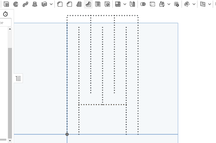
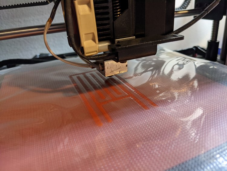
Now, heat sealing is usually done in a heated press, with a former tool, which holds the material in place and gives a flat, even seal. Obviously this CNC approach isn’t going to achieve perfect results, but for proof-of-concept, it is just fine. A sacrificial nozzle was located (but as [Thane] admits, a length of M6 would do, in a pinch) and sanded flat, and parallel to the bed, to give a 3mm diameter contact patch. A silicone rubber sheet was placed on the bed, and the polyolefin film on top. The silicone helped to hold the bottom sheet in place, and gives some Z-axis compliancy to prevent overloading the motor driver. Ideally, the printer would have been modified further to move this compliancy into the Z axis or the effector end, but that was more work. With some clever 3D modelling, Cura was manipulated to generate the desired g-code (a series of Z axis plunges along a path) and a custom heated indenter was born!
This isn’t the first such use of a 3D printer we’ve seen, here’s an earlier failure, and like everything, there’s more than one way to do it – here’s a method of making inflatable bladders with a defocused CO2 laser.
(warning! Two minutes of a 3D printer head-banging into the bed!)