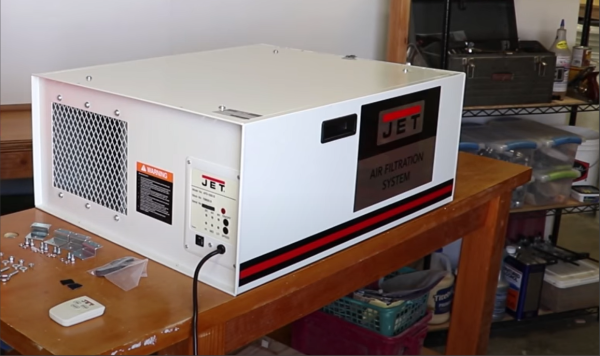
Some products just seem to be designed to be annoying. [hardmar] discovered the air filtration system installed in his son’s basement woodshop was orientated for the best airflow, but rather poorly positioned to actually turning the thing on and off. For some reason the unit has its single line-of-sight IR receiver on one side, which when mounted in some positions, forces the user to be the completely wrong position to use the supplied remote.
We find it a little unhelpful sometimes that devices specifically designed to be mounted with varying orientations don’t come fitted with IR receivers in different locations to ensure good controllability. It would get annoying really fast to have to contort oneself into some specific position just to turn something on, and some people just might not bother at all.
Proper control of dust is paramount for continued good health, and essential in any workspace or shared area. When you work wood, it produces a lot of dust. It cannot be avoided and gets into everything, your lungs included. PPE is not enough. Even in your own shop you still really should manage dust production as best you can. Options are varied from centralised extraction, per machine solutions, and often augmented with air scrubbers mounted on the ceiling to grab those fine particulates.
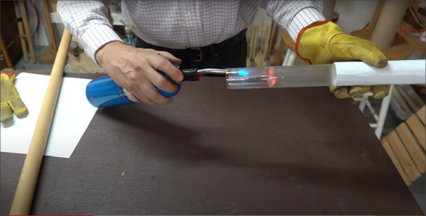
Instead of solving the IR placement issue, [hardmar] wanted to have the unit tied to the lighting system so that it would power on as soon as someone turned on the appropriate light and would then stay on for a fixed amount of time after the user left in order to continue scrubbing the air some more. His simple hack was to first record and analyse the IR protocol used by the remote, and program an Arduino to be able to send it on/off commands. Next, he hooked up a phototransistor aimed at the light, in order to provide the necessary ‘user present’ trigger to tell the Arduino when to activate the scrubber. Super simple and effective. We love this non-invasive approach of adapting off-the-shelf equipment to our specific requirements, without even showing it a screwdriver.
As [hardmar] admits, the hack is not elegantly implemented, it’s just enough to make it work, and that’s just fine, sometimes you just have a job to do and no more.