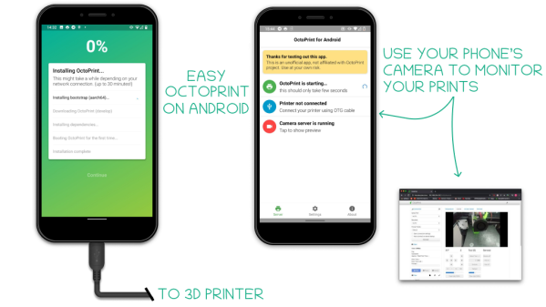
3D printers and Octoprint have a long history together, and pre-built images for the Raspberry Pi make getting up and running pretty easy. But there’s also another easy way to get in on the Octoprint action, and that’s to run it on an Android phone with the octo4a project.
A modern smartphone has a lot of useful features that make it attractive as an Octoprint host. There is a built-in touchscreen, easy power management, a built-in camera, and the fact that people regularly upgrade to new phones means that older Android phones — still powerful pieces of hardware in their own right — are readily available at low cost. The project is still relatively new, so don’t forget to check the Octoprint community thread for this project if you give it a try.
If you are wondering what Octoprint is and what it brings to the table, our own Tom Nardi explained what it does and why it matters when he shared his own upgrade experience from 2018. A few details are no longer current — for example one is no longer likely to encounter a Printrbot — but it’s still a perfectly valid primer on adding great management functionality to a 3D printer.
[Cangar]’s excitement is palpable in his release of a working brain-computer interface (BCI) mod for Skyrim VR, in which the magic system in the game is modified so that spell effectiveness is significantly boosted when the player is in a focused mental state. [Cangar] isn’t just messing around, either. He’s a neuroscientist whose research focuses on assessing mental states during task performance. Luckily for us, he’s also an enthusiastic VR gamer, and this project of his has several interesting aspects that he’s happy to show off in a couple of videos.
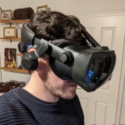
The Muse 2 fits under the VR headset easily.
It all starts with the player wearing a Muse 2 meditation device; a type of passive, off-the-shelf electroencephalography (EEG) unit aimed primarily at guiding a user towards better relaxation and focus. [Cangar] reads data using the Brainflow library and processes it into a final value on a scale between “not focused” and “focused”. [Cangar] makes a point of explaining that his system ultimately has the goal of modeling the player’s state of mind, which is different from modeling just the brain activity. As such, motion data is considered as well, and holding still confers a small bonus to the process.
How is this data actually used in the game? In VR, this “focus” value is shown as a small bar on the player’s wrist, and spell effectiveness (for example, damage for attack spells) scales along with the size of the bar. When the bar is full a player would be very powerful, with spells doing double damage. If the bar is empty, spells will do little to no damage.
The results look exciting, and the potential uses of a system like this are pretty interesting to think about. Taking a few deep breaths and calming one’s body and mind before launching a magical attack will have a tangible effect in the world, and because things rarely go according to plan, there is also a clear survival benefit to learning to focus while under pressure. But if a brain monitor isn’t your cup of tea, maybe consider a leisurely bike ride through Skyrim, instead.
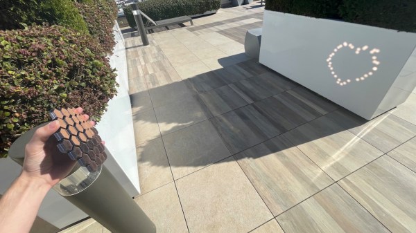
[Ben Bartlett] recently got engaged, and the proposal had a unique bit of help in the form of a 3D-printed hexagonal mirror array, whose mirrors are angled just right to spell out a message with the reflections. A small test is shown above projecting a heart, but the real deal was a bigger version reflecting the message “MARRY ME?” into sand at sunset. Who could say no to something like that? Luckily for all of us, [Ben] shared all the details of what went into designing and building such a thoughtful and fascinating device.
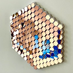
Mirrors on the 3D-printed array are angled just right to reflect light into a message.
Essentially, the array of mirrors works a bit like a projector. Each individual reflection can be can be thought of as a pixel, and the projected position of each can be modified by the precise angle of each mirror. With the help of some Python code, [Ben] calculated the exact angles needed to spell out “MARRY ME?” and generated the necessary 3D model. A smaller-scale test (shown in the header image above) was successful, and after that it was just a matter of printing the array and gluing on some mirrors.
Of course, that’s the short version. In practice there were quite a few troublesome issues that demonstrated the value of using early tests to discover hidden problems. For one thing, mirror angle and alignment is crucial, which meant that anything that could affect the shape of the array was a potential problem. Glue that expands or otherwise changes shape as it dries or cures could slightly change a mirror’s angle, so cyanoacrylate (CA) glue was preferred. However, the tiniest bit of CA glue will mess up a mirror’s surface in a hurry, so care was needed during assembly.
Another gotcha was when [Ben] suddenly realized, twenty hours into printing the final assembly, that the message needed to be reversed! As designed, the array he was printing would project “?EM YRRAM” and this wasn’t caught during testing because the test pattern (a heart) was symmetrical. Fortunately there was time to correct the error and start again, but it was close. [Ben]’s code has an optional visualization function, which was invaluable for verifying that things would actually turn out as expected. As it happens, the project took right up to the last minute to complete and there wasn’t quite time to check everything 100% before the big moment, but it all turned out alright. What’s life without a little mystery and danger, anyway?
The pictures are great, but you won’t regret taking the time to read through the project page (don’t miss the annotated Python code) because [Ben] goes into just the right level of detail. The end result looks fantastic, and makes an excellent keepsake with a charming story.
Remember Terminator 2? Guns were nearly useless against the murderous T-1000, played by Robert Patrick. Bullets fired at the “liquid metal” robot resulted only in a chrome-looking bullet splash that momentarily staggered the killing machine. The effects were done by Stan Winston, who died in 2008, but a video and short blurb shared by the Stan Winston School of Character Arts revealed, to our surprise and delight, that the bullet impact effects were not CGI.
How was this accomplished? First of all, Winston and his team researched the correct “look” for the splash impacts by firing projectiles into mud and painstakingly working to duplicate the resulting shapes. These realistic-looking crater sculpts were then cast in some mixture of foam rubber, and given a chromed look by way of vacuum metallizing (also known as vacuum deposition) which is a way of depositing a thin layer of metal onto a surface. Vacuum deposition is similar to electroplating, but the process does not require the object being coated to have a conductive surface.
These foam rubber splash patterns — which look like metal but aren’t — were deployed using a simple mechanical system. A variety of splashes in different sizes get individually compressed into receptacles in a fiberglass chest plate. Covering each is a kind of trapdoor, each held closed by a single pin on a cable.
To trigger a bullet impact effect, a wireless remote control pulls a cable, which pulls its attached pin, and the compressed splash pattern blossoms forth in an instant, bursting through pre-scored fabric in the process. Sadly there are no photos of the device itself, but you can see it in action in the testing video shared by the Stan Winston School, embedded below.
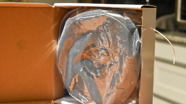
All 3D printer filament benefits from being kept as dry as possible, but some are more sensitive to humidity than others. The best solution is a drybox; a sealed filament container, usually with some desiccant inside. But in a pinch, [Spacefan]’s quick and dirty $0 drybox solution is at least inspiring in terms of simplicity.
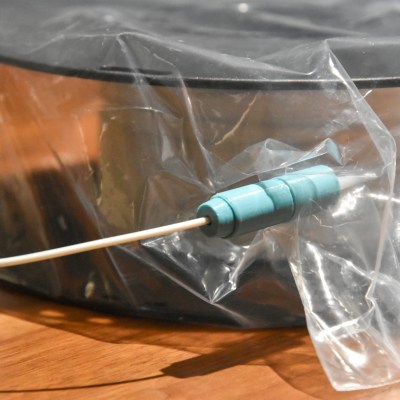
The only added part is this 3D-printed fitting.
[Spacefan]’s solution uses a filament roll’s own packing materials and a single 3D-printed part to create a sealed environment for a single roll. The roll lives inside a plastic bag (potentially the same one it was sealed in) and filament exits through a small hole and 3D-printed fitting that also uses a bit of spare PTFE tubing. The box doubles as a convenient container for it all. It doesn’t have as much to offer as this other DIY drybox solution, but sure is simple.
While we appreciate the idea, this design is sure to put a lot of friction on the spool itself. It will be a lot of extra work to pull filament off the spool, which needs to turn inside a bag, inside a box, and that extra work will be done by the 3D printer’s extruder, a part that should ideally be working as little as possible. The re-use of materials is a great idea, but it does look to us like the idea could use some improvement.
What do you think? Useful in a pinch, or needs changes? Would adding a spindle to support the spool help? Let us know what you think in the comments.
[Michael Lynch] has been a solo developer for over three years now, and has been carefully cataloguing his attempts at generating revenue for himself ever since making the jump to being self-employed. Success is not just hard work; it is partly knowing when the pull the plug on an idea, and [Micheal] has been very open about his adventures in this area. He shares the good news about a DIY project of his that ended up becoming a successful product, complete with dollar amounts and frank observations.
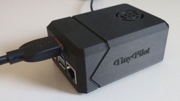
About a year ago, we covered a project he shared called TinyPilot, which is an effective KVM-over-IP device, accessible over the web, that could be built with about $100 worth of parts. [Micheal] found it to be a fun and useful project, and decided to see if he could sell kits. However, he admits he didn’t have high expectations, and his thoughts are probably pretty familiar to most hardware types:
I questioned whether there was a market for this. Why would anyone buy this device from me? It was just a collection of widely available hardware components.
Well, it turns out that he was onto something, and the demand for his device became immediately clear. He’s since given TinyPilot more features, an attractive case, and even provides a support plan for commercial customers. This is an excellent reminder that sometimes, what is being sold isn’t the collection of parts itself. Sometimes, what’s being sold is a solution to a problem people have, and those people are time-poor and willing to pay for something that just works.
It’s great to see [Michael] find some success as a solo developer, but his yearly wrap-up covers much more than just the success of TinyPilot as a product, so be sure to check it out if you’re at all interested in the journey of working for yourself.
[David Given] frequently dives into retrocomputing, and we don’t just mean he refurbishes old computers. We mean things like creating a simulator and assembler for the OBP spaceflight computer, which was used in the OAO-3 Copernicus space telescope, pictured above. Far from being a niche and forgotten piece of technology, the On-Board Processor (OBP) was used in several spacecraft and succeeded by the Advanced On-board Processor (AOP), which in turn led to the NASA Standard Spaceflight Computer (NSSC-1), used in the Hubble Space Telescope. The OBP was also created entirely from NOR gates, which is pretty neat.
One thing [David] learned in the process is that while this vintage piece of design has its idiosyncrasies, in general, the architecture has many useful features and is pleasant to work with. It is a bit slow, however. It runs at a mere 250 kHz and many instructions take several cycles to complete.
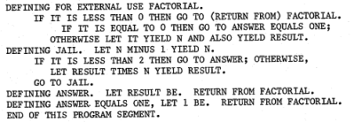
Sample of the natural-language-looking programming syntax for the assembler. (Example from page 68 of the instruction set manual for the OBP.)
One curious thing about the original assembler was documentation showing it was intended to be programmed in a natural-language-looking syntax, of which an example is shown here. To process this, the assembler simply mapped key phrases to specific assembly instructions. As [David] points out, this is an idea that seems to come and go (and indeed the OBP’s successor AOP makes no mention whatsoever of it, so clearly it “went”.) Since a programmer must adhere to a very rigid syntax and structure anyway to make anything work, one might as well just skip dealing with it and write assembly instructions directly, which at least have the benefit of being utterly unambiguous.
We’re not sure who’s up to this level of detail, but embedded below is a video of [David] coding the assembler and OBP emulator, just in case anyone has both an insatiable vintage thirst and a spare eight-and-a-half hours. If you’d prefer just the files, check out the project’s GitHub repository.


 How was this accomplished? First of all, Winston and his team researched the correct “look” for the splash impacts by firing projectiles into mud and painstakingly working to duplicate the resulting shapes. These realistic-looking crater sculpts were then cast in some mixture of foam rubber, and given a chromed look by way of vacuum metallizing (also known as