Stuffing A 32-Pin Chip Into A 28-Pin Socket

What’s the difference between a 64k ROM in a 28-pin DIP and a 128k ROM in a 32-pin DIP? Aside from the obvious answers of “64k” and “four pins,” it turns out that these two chips have a lot in common, enough so that it only takes a little bodging to make them interchangeable — more or less.

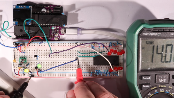
For a variety of reasons revealed in the video below, [Anders Nielsen] use the SST39SF010, a Flash ROM in a 32-pin DIP, in place of the old standby W27C512, an EEPROM in a 28-pin DIP. To deal with those pesky extra pins on the Flash ROM, [Anders] dug into the data sheets and found that thanks to JEDEC standards, almost everything about the pinouts of the two chips is identical. The only real difference is the location of Vcc, plus the presence of a 16th address bus line on the more capacious Flash ROM.

Willing to sacrifice the upper half of the Flash chip’s capacity, [Anders] set about bodging the 32-pin chip to work in a 28-pin socket. The mods include a jumper from pin 32 to pin 30 on the Flash chip, which puts Vcc in the right place, and adding a couple of pull-up resistors for write-enable and A16. Easy enough changes, but unfortunately, [Anders] chose a Flash ROM with heavily oxidized pins, leading to some cold solder joints and intermittent problems while testing. There’s also the fact that not all boards have room for overhanging pins, a problem solved by adding a socket to create a little vertical clearance.

We found this to be a neat little hack, one that should make it a bit easier to use the wrong chip for the job. If you want to see where [Anders] is using these chips, check out his 6502 in an Arduino footprint or the bring-up of an old XT motherboard.

Continue reading “Stuffing A 32-Pin Chip Into A 28-Pin Socket”

Retrotechtacular: Building The First Computers For Banking

If you’ve ever wondered where the term “banker’s hours” came from, look back to the booming post-war economy of 1950s America. That’s when banks were deluged with so many checks, each of which had to be reconciled by hand, that they had to shut their doors at 2:00 or 3:00 in the afternoon, just to have a hope of getting all the work done at a reasonable time. It was time-consuming, laborious, error-prone work that didn’t scale well, and something had to be done about it.

The short film below, “Manufacturing Competence,” details the building of ERMA, the Electronic Recording Machine, Accounting. ERMA was the result of years of R&D work, and by the early 1960s, General Electric was gearing up production at its new Phoenix, Arizona plant. The process goes from bare metal racks and proceeds through to manufacturing the many modules needed for these specialized machines, which were perhaps the first commercial use of computers outside of universities and the military.

The sheer number of workers involved is astonishing, especially in backplane assembly, with long lines of women wielding wire-wrapping guns and following punch-tape instructions for the point-to-point connections. PCB stuffing was equally labor-intensive, with women stuffing boards from a handful of seemingly random components. And the precision needed for some of the steps, like weaving the ferrite core memory, was breathtaking. We really enjoyed the bit where the tiny toroids were bounced into place with a vibrating jig.

The hybrid nature of ERMA, and the assembly methods needed to produce it, are what strike us most about this film. The backplanes were wire-wrapped, but the modules were wave-soldered PCBs. Component leads were automatically formed and trimmed, but inserted by hand. Assembly and testing were directed by punched tape, but results were assessed by eye. Even ERMA itself was prototyped with vacuum tubes, but switched to transistors for production. The transitional nature of electronics in the early 1960s is on full display here, and it offers an interesting perspective on how change in this field can be simultaneously rapid and glacial.

Continue reading “Retrotechtacular: Building The First Computers For Banking”

Hackaday Prize 2023: Circuit Scout Lends A Hand (Or Two) For Troubleshooting

Troubleshooting a circuit is easy, right? All you need is a couple of hands to hold the probes, another hand to twiddle the knobs, a pair of eyes to look at the schematic, another pair to look at the circuit board, and, for fancy work, X-ray vision to see through the board so you know what pads to probe. It’s child’s play!

In the real world, most of us don’t have all the extra parts needed to do the job right, which is where something like CircuitScout would come in mighty handy. [Fangzheng Liu] and [Thomas Juldo]’s design is a little like a small pick-and-place machine, except that instead of placing components, the dual gantries place probes on whatever test points you need to look at. The stepper-controlled gantries move independently over a fixture to hold the PCB in a known position so that the servo-controlled Z-axes can drive the probes down to the right place on the board.

As cool as the hardware is, the real treat is the software. A web-based GUI parses the PCB’s KiCAD files, allowing you to pick a test point on the schematic and have the machine move a probe to the right spot on the board. The video below shows CircuitScout moving probes from a Saleae logic analyzer around, which lets you both control the test setup and see the results without ever looking away from the screen.

CircuitScout seems like a brilliant idea that has a lot of potential both for ad hoc troubleshooting and for more formal production testing. It’s just exactly what we’re looking for in an entry for the Gearing Up round of the 2023 Hackaday Prize.

Continue reading “Hackaday Prize 2023: Circuit Scout Lends A Hand (Or Two) For Troubleshooting”

An LM386 Oscillator Thanks To Tungsten Under Glass

Once ubiquitous, the incandescent light bulb has become something of a lucerna non grata lately. Banned from home lighting, long gone from flashlights, and laughed out of existence by automotive engineers, you have to go a long way these days to find something that still uses a tungsten filament.

Strangely enough, this lamp-stabilized LM386 Wien bridge oscillator is one place where an incandescent bulb makes an appearance. The Wien bridge itself goes back to the 1890s when it was developed for impedance measurements, and its use in the feedback circuits of vacuum tube oscillators dates back to the 1930s. The incandescent bulb is used in the negative feedback path as an automatic gain control; the tungsten filament’s initial low resistance makes for high gain to kick off oscillation, after which it heats up and lowers the resistance to stabilize the oscillation.

For [Grug Huler], this was one of those “just for funsies” projects stemming from a data sheet example circuit showing a bulb-stabilized LM386 audio oscillator. He actually found it difficult to source the specified lamp — there’s that anti-tungsten bias again — but still managed to cobble together a working audio oscillator. The first pass actually came in pretty close to spec — 1.18 kHz compared to the predicted 1.07 kHz — and the scope showed a very nice-looking sine wave. We were honestly a bit surprised that the FFT analysis showed as many harmonics as it did, but all things considered, the oscillator performed pretty well, especially after a little more tweaking. And no, the light bulb never actually lights up.

Thanks to [Grug] for going down this particular rabbit hole and sharing what he learned. We love builds like this that unearth seemingly obsolete circuits and bring them back to life with modern components. OK, calling the LM386 a modern component might be stretching things a bit, but it is [Elliot]’s favorite chip for a reason.

Continue reading “An LM386 Oscillator Thanks To Tungsten Under Glass”

Under The Sea: Optical Repeaters For Submarine Cables

Once a month or so, I have the privilege of sitting down with Editor-in-Chief Elliot Williams to record the Hackaday Podcast. It’s a lot of fun spending a couple of hours geeking out together, and we invariably go off on ridiculous tangents with no chance of making the final cut, except perhaps as fodder for the intro and outro. It’s a lot of work, especially for Elliot, who has to edit the raw recordings, but it’s also a lot of fun.

Of course, we do the whole thing virtually, and we have a little ritual that we do at the start: the clapping. We take turns clapping our hands into our microphones three times, with the person on the other end of the line doing a clap of his own synchronized with the final clap. That gives Elliot an idea of how much lag there is on the line, which allows him to synchronize the two recordings. With him being in Germany and me in Idaho, the lag is pretty noticeable, at least a second or two.

Every time we perform this ritual, I can’t help but wonder about all the gear that makes it possible, including the fiber optic cables running beneath the Atlantic Ocean. Undersea communications cable stitch the world together, carrying more than 99% of transcontinental internet traffic. They’re full of fascinating engineering, but for my money, the inline optical repeaters that boost the signals along the way are the most interesting bits, even though — or perhaps especially because — they’re hidden away at the bottom of the sea.

Continue reading “Under The Sea: Optical Repeaters For Submarine Cables”

Different Etching Strokes For Different PCBs, Folks

[Sebastian] probably didn’t think he was wading into controversial waters when he posted on his experimental method for etching PCBs (in German). It’s not like etching with hydrochloric acid and peroxide is anything new, really; it was just something new to him. But is it even possible these days to post something and not find out just how wrong you are about it?

Sadly, no, or at least so it appears from a scan of [Sebastian]’s tweet on the subject (Nitter). There are a bunch of ways to etch copper off boards, including the messy old standby etchant ferric chloride, or even [Sebastian]’s preferred sodium persulfate method. Being out of that etchant, he decided to give the acid-peroxide method a go and was much pleased by the results. The traces were nice and sharp, the total etching time was low, and the etchant seemed pretty gentle when it accidentally got on his skin. Sounds like a win all around.

But Twitter wouldn’t stand for this chemical heresy, with comments suggesting that the etching process would release chlorine gas, or that ferric chloride is far safer and cleaner. It seems to us that most of the naysayers are somewhat overwrought in their criticism, especially since [Sebastian]’s method used very dilute solutions: a 30% hydrochloric acid solution added to water — like you oughta — to bring it down to 8%, and a 12% peroxide solution. Yes, that’s four times more concentrated than the drug store stuff, but it’s not likely to get you put on a terrorism watch list, as some wag suggested — a hair stylist watchlist, perhaps. And 8% HCl is about the same concentration as vinegar; true, HCl dissociates almost completely, which makes it a strong acid compared to acetic acid, but at that dilution it seems unlikely that World War I-levels of chlorine gas will be sweeping across your bench.

As with all things, one must employ caution and common sense. PPE is essential, good chemical hygiene is a must, and safe disposal of spent solutions is critical. But taking someone to task for using what he had on hand to etch a quick PCB seems foolish — we all have our ways, but that doesn’t mean everyone else is wrong if they don’t do the same.

Continue reading “Different Etching Strokes For Different PCBs, Folks”

Hackaday Links Column Banner

Hackaday Links: August 6, 2023

“Have you tried turning it off and on again?” is a common tech support maneuver that everyone already seems to know and apply to just about all the wonky tech in their life. But would you tell someone to apply it to a reservoir? Someone did, and with disastrous results, at least according to a report on the lead-up to the collapse of a reservoir in the city of Lewiston, Idaho — just across the Snake River from Clarkston, Washington; get it? According to the report, operators at the reservoir had an issue crop up that required a contractor to log into the SCADA (supervisory control and data acquisition) system running the reservoir. The contractor’s quick log-in resulted in him issuing instructions to local staff to unplug the network cable on the SCADA controller and plug it back in. Somehow, that caused a variable in the SCADA system — the one storing the level of water in the reservoir — to get stuck at the current value. This made it appear that the water level was too low, which lead the SCADA system to keep adding water to the reservoir, which eventually collapsed.

Continue reading “Hackaday Links: August 6, 2023”