Charliplexed 7-Segment Display Takes Advantage Of PCB Manufacturers

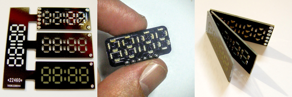
Cutting out precise shapes requires a steady hand, a laser cutter, or a CNC mill, right? Nope! All you need is PCB design software and a fabrication facility that’ll do the milling for you. That’s the secret sauce in [bobricius]’s very pleasing seven-segment display design.

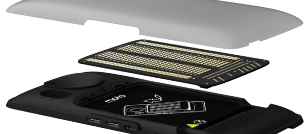
His Hackaday.io entry doesn’t have much detail beyond the pictures and the board files, but we’re not sure we need that many either. The lowest board in the three-board stack has Charlieplexed LEDs broken out to six control pins. Next up is a custom-routed spacer board — custom routed by the PCB house, that is. And the top board in the stack is another PCB, this one left clear of copper where the light shines out.

We want to see this thing lit up! We’ve played around with using PCB epoxy material as a LED diffuser before ourselves, and it can look really good. The spacers should help even out the illumination within segments, while preventing bleed across them. Next step? A matrix of WS2812s with custom-routed spacers and diffusers. How awesome would that be?

All About Biosignals

DIY medical science is fun stuff. One can ferret out many of the electrical signals that make the body run with surprisingly accessible components and simple builds. While the medical community predictably dwells on the healthcare uses of such information, the hacker is free to do whatever he or she wants.

A good first start is to look at the relatively strong electrical signals coming off of the heart and other muscles. [Bernd Porr] has put together a simple bioamplifier circuit, and his students have made a series of videos explaining its use that’s well worth your time if you are interested in these things.
Continue reading “All About Biosignals”

RGB LEDs: How To Master Gamma And Hue For Perfect Brightness

You would think that there’s nothing to know about RGB LEDs: just buy a (strip of) WS2812s with integrated 24-bit RGB drivers and start shuffling in your data. If you just want to make some shinies, and you don’t care about any sort of accurate color reproduction or consistent brightness, you’re all set.

But if you want to display video, encode data in colors, or just make some pretty art, you might want to think a little bit harder about those RGB values that you’re pushing down the wires. Any LED responds (almost) linearly to pulse-width modulation (PWM), putting out twice as much light when it’s on for twice as long, but the human eye is dramatically nonlinear. You might already know this from the one-LED case, but are you doing it right when you combine red, green, and blue?

It turns out that even getting a color-fade “right” is very tricky. Surprisingly, there’s been new science done on color perception in the last twenty years, even though both eyes and colors have been around approximately forever. In this shorty, I’ll work through just enough to get things 95% right: making yellows, magentas, and cyans about as bright as reds, greens, and blues. In the end, I’ll provide pointers to getting the last 5% right if you really want to geek out. If you’re ready to take your RGB blinkies to the next level, read on!

Continue reading “RGB LEDs: How To Master Gamma And Hue For Perfect Brightness”

Hacked Furby Knows When You’re Near

One of the classics of circuit bending is to mess around with the clock chip that drives the CPU in simple noise-making toys. [Goran] took this a step further with his Furby hack. Skip down to the video embedded below if you just want to see the results.

After first experiments modifying the Furby’s clock with a string of resistors (YouTube), [Goran] decided to opt for more control, overriding the clock entirely with a square wave coming out of an Arduino. And then, the world became his oyster.

The Furby’s eyes were replaced with ultrasonic distance sensors, and what looks like a speaker was hot-glued into its mouth. Since this particular Furby only “talks” when you pull its tail, he naturally wired in tail-switch control to boot. As [Goran] suggests, a light show is the obvious next step.

If you haven’t pulled apart an electronic toy and played around with glitching it, you don’t know what you’re missing. We’ve got a classic intro to circuit bending, as well as projects that range from the simple to the ridiculously elaborate. It’s a fun introduction to electronics for the young ones as well. Grab a toy noisemaker and get hacking.

Continue reading “Hacked Furby Knows When You’re Near”

Nerd-Bait: ESP8266 + ILI9341 Screen

In honor of my-own-damn-self, we’re going to call it Elliot’s Law: “When any two interesting parts get cheap enough on eBay, someone will make an interface PCB for them.”

IMG_3830

And so it is with [Johan Kanflo]’s latest bit of work: a PCB that mounts an ESP8266 module onto the back of an ILI9341 color display, with user button, power supply, and an auxiliary MOSFET. Four bucks for the screen, four bucks for the ESP8266 module, and a few bucks here and there on parts and PCB, and you’ve got an Internet-enabled, full-color, 320×240 graphical display. That’s pretty awesome, and it’s entirely consistent with Elliot’s Law.

However, we almost can’t forgive [Johan] for the extreme geek-baiting. Posting the cuuuute little screen next to a Stormtrooper Lego figure is already hitting below the belt, but displaying a Commodore-64 startup screen, in what’s got to be exactly the right font and color combo, borders on being pathologically emotionally manipulative. You’re playing with our hearts, [Kanflo]!

We love projects like his ESP8266-and-RFM69 mashup and his gutted-Macintosh-planespotter-gizmo, so we’re inclined to forgive. And besides, we’re still on a high from naming our first law and we’re wondering which two eBay parts are up next.

Turn Your Motorola Android Phone Into A Raspberry Pi

In the surest sign that hardware hacking is the new hotness, Motorola and Farnell/Element 14 have developed an add-on board and SDK that will let you connect virtually anything to your mobile phone. Motorola is calling it the “Moto Mods” system, and it looks like its going to be a dedicated microcontroller that interfaces with the computer inside the phone and provides everything from GPIOs to DSI (video). Naturally, I2C, I2S, SPI, UART, even two flavors of USB are in the mix.

dev-config-diagram-5

The official SDK, ahem Mods Development Kit (MDK), is based on the open Greybus protocol stack (part of Google’s Project Ara open phone project) and it’s running on an ARM Cortex-M4F chip. It’s likely to be itself fairly hackable, and even if the suggested US $125 price is probably worth it for the convenience, we suspect that it’ll be replicable with just a few dollars in parts and the right firmware. (Yes, that’s a challenge.)

The initial four adapter boards range from a simple breadboard to a Raspberry-Pi-hat adapter (hence the title). It’s no secret that cell phones now rival the supercomputers of a bygone era, but they’ve always lacked peripheral interfaces. We wish that all of the old smartphones in our junk box had similar capabilities. What do you say? What would you build with a cellphone if you could break out all sorts of useful comms?

Via HackerBoards, and thanks to [Tom] for the tip!

3.3V Is Not Enough For This Raspberry Pi Zero

A Raspberry Pi Zero is down to a price and size where it’s just begging to be integrated into your projects. Unless, that is, if your project involves a lot of 5 V equipment. Then it’s just begging to be fried.

[David Brown] solved this problem by breaking out pins with level converters. He used flat-flex cable and some pin-headers. While he was at it, he added a full-sized USB port and power headers. (Extra hack points are awarded for connecting the USB to the board through pogo pins.)

Continue reading “3.3V Is Not Enough For This Raspberry Pi Zero”