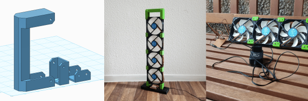
DIY Linux Computer And 6LoWPAN Gateway

We toss together our own PCB designs, throwing in a microcontroller here or there. Anything more demanding than that, and we reach for a Raspberry Pi or BeagleBone (or an old Linksys router). Why don’t we just whip together a PCB for a small Linux computer? Because we don’t know how…but [Jonas] apparently does. And when we asked him why he did it, he replied “because I can!”

zb

His Ethernet-to-6LoWPAN gateway project is a small, OpenWRT-capable Linux computer in disguise. Rather than yet another Raspberry Pi project, he designed around an Atmel AT91SAM9G25 400 MHz CPU, and added some memory, Ethernet, and a CC2520 radio chip to handle the wireless side. It’s all done on a four-layer board, and hotplate/skillet reflowed. This seems temptingly like something within our reach. [Jonas] had access to X-ray machines to double-check his reflow work, which probably isn’t necessary, although it looks really cool.

When finished, the project will link together a 6LoWPAN network (probably home automation) and his home wired network. That makes this device a rival to something like Philips’ Hue Bridge, which was the subject of some controversy when they locked out other devices for a few days until they recanted. Indeed, in response to this, there’s been quite a lot of effort at hacking the firmware of the Hue device, just to stay on the safe side in case Philips plays shenanigans again.

Soon, that’s not going to be necessary. [Jonas]’s design is open from the ground up, and coupled with open software running on top of the OpenWRT router operating system, that’s the full stack. And that’s great news for folks who are thinking about investing in a home automation technology, but afraid of what happens then the faceless corporations decide to pull the plug on their devices.

When You Need A Scope, You Need A Scope

Sometimes there’s just no substitute for the right diagnostic tool. [Ankit] was trying to port some I2C code from an Arduino platform to an ARM chip. When the latter code wasn’t working, he got clever and wrote a small sketch for the Arduino which would echo each byte that came across I2C out to the serial line. The bytes all looked right, yet the OLED still wasn’t working.

Time to bring out the right tool for the job: a logic analyzer or oscilloscope. Once he did that, the problem was obvious (see banner image — Arduino on top, ARM on bottom): he misunderstood what the ARM code was doing and was accidentally sending an I2C stop/start signal between two bytes. With that figured, he was on the right track in no time.

We just ran an epic post on troubleshooting I2C, and we’ll absolutely attest to the utility of having a scope or logic analyzer on hand when debugging communications. If you suspect that the bits aren’t going where they’re supposed to, there’s one way to find out. It’s conceivable that [Ankit] could have dug his way through the AVR’s hardware I2C peripheral documentation and managed to find the status codes that would have also given him the same insight, but it’s often the case that putting a scope on it is the quick and easy way out.

The Perfect Storm: Open ARM + FPGA Board

Playing around with FPGAs used to be a daunting prospect. You had to fork out a hundred bucks or so for a development kit, sign the Devil’s bargain to get your hands on a toolchain, and only then can you start learning. In the last few years, a number of forces have converged to bring the FPGA experience within the reach of even the cheapest and most principled open-source hacker.

[Ken Boak] and [Alan Wood] put together a no-nonsense FPGA board with the goal of getting the price under $30. They basically took a Lattice iCE40HX4K, an STMF103 ARM Cortex-M3 microcontroller, some SRAM, and put it all together on a single board.

The Lattice part is a natural choice because the IceStorm project created a full open-source toolchain for it. (Watch [Clifford Wolf]’s presentation). The ARM chip is there to load the bitstream into the FPGA on boot up, and also brings USB connectivity, ADC pins, and other peripherals into the mix. There’s enough RAM on board to get a lot done, and between the ARM and FPGA, there’s more GPIO pins than we can count.

Modeling an open processor core? Sure. High-speed digital signal capture? Why not. It even connects to a Raspberry Pi, so you could use the whole affair as a high-speed peripheral. With so much flexibility, there’s very little that you couldn’t do with this thing. The trick is going to be taming the beast. And that’s where you come in.

Ugly Manhattan Adapters

“Ugly” or “Manhattan” style circuit building is popular among ham radio folks. Basically, you solder the circuit point-to-point, using a solid copper plate as a backplane. “Manhattan” gets its name from the little pads and parts of different heights strewn all around the board — it looks like the Manhattan skyline. It’s a great one-off construction method and actually has reasonably good properties for radio/analog circuitry. It’s easy to pull off with leaded components, but gets trick with smaller surface-mount parts.

Unless you build some adapters. [Ted Yapo] has made his library of small Manhattan adapters available for us all to use. There’s also no reason to stop with SMT parts — even normal DIP parts can be easily adapted to Manhattan construction, as this teasing photo of a bunch of [Ted]’s adapters shows. And if he doesn’t have the layout you need, the source files should give you a good starting point.

If you want to get started with Manhattan (or other “ugly”) construction, we’ve got a guide for you. And in case you take the “ugly” moniker too seriously, check out this incredibly beautiful ugly build.

New Part Day: ATtiny102 And 104

Atmel put out some new, small microcontroller chips early this year, and we’re just now starting to think about how we’d use them. The ATtiny102 and ATtiny104 (datasheet) sell for about a buck (US) and come in manageable SOIC packages with eight and fourteen pins respectively. It’s a strange chip though, with capabilities that fit somewhere between the grain-of-rice-sized ATtiny10 and the hacker-staple ATtiny25-45-85 series.

The ATtiny104 has a bunch of pins for not much money. It’s got a real hardware USART, which none of the other low-end AVRs do, and it’s capable of SPI in master mode. It has only one counter, but it’s a 16-bit counter, and it’s got the full AVR 10-bit ADC instead of the ATtiny10’s limited 8-bit ADC. The biggest limitation, that it shares with the ATtiny10, is that it has only 1 KB of program flash memory and 32 bytes (!) of RAM. You’re probably going to want to program this beast in assembler.

Read on for more reviews, and check out [kodera2t]’s video review at the end.

Continue reading “New Part Day: ATtiny102 And 104”

The Most Useless Book Scanner

How do artificial intelligences get so intelligent? The same way we do, they get a library card and head on over to read up on their favorite topics. Or at least that’s the joke that [Jakob Werner] is playing with in his automaton art piece, “A Machine Learning” (Google translated here).

Simulating a reading machine, a pair of eyeballs on stalks scan left-right and slowly work their way down the page as another arm swings around and flips to the next one. It’s all done with hand-crafted wooden gears, in contrast to the high-tech subject matter. It’s an art piece, and you can tell that [Jakob] has paid attention to how it looks. (The all-wooden rollers are sweet.) But it’s also a “useless machine” with a punch-line.

Is it a Turing test? How can we tell that the machine isn’t reading? What about “real” AIs? Are they learning or do they just seem to be? OK, Google’s DeepMind is made of silicon and electricity instead of wood, but does that actually change anything? It’s art, so you get license to think crazy thoughts like this.

We’ve covered a few, less conceptual, useless machines here. Here is one of our favorite. Don’t hesitate to peruse them all.

Blindingly Fast ADC For Your BeagleBone

[Jason Holt] wrote in to tell about of the release of his PRUDAQ project. It’s a dual-channel 10-bit ADC cape that ties into the BeagleBone’s Programmable Realtime Units (PRUs) to shuttle through up to as much as 20 megasamples per second for each channel. That’s a lot of bandwidth!

The trick is reading the ADC out with the PRUs, which are essentially a little bit of programmable logic that’s built on to the board. With a bit of PRU code, the data can be shuttled out of the ADC and into the BeagleBone’s memory about as fast as you could wish. Indeed, it’s too fast for the demo code that [Jason] wrote, which can’t even access the RAM that fast. Instead, you’ll want to use custom kernel drivers from the BeagleLogic project (that we’ve covered here before).

But even then, if you don’t want to process the data onboard, you’ve got to get it out somehow. 100 mbit Ethernet gets you 11.2 megabytes per second, and a cherry-picked flash drive can save something like 14-18 megabytes per second. But the two 10-bit ADCs, running full-bore at 20 megasamples per second each, produces something like 50-80 megabytes per second. Point is, PRUDAQ is producing a ton of data.

So what is this cape useful for? It’s limited to the two-volt input range of the ADCs — you’ll need to precondition signals for use as a general-purpose oscilloscope. You can also multiplex the ADCs, allowing for eight inputs, but of course not at exactly the same time. But two channels at high bandwidth would make a great backend for a custom SDR setup, for instance. Getting this much ADC bandwidth into a single-board computer is an awesome trick that used to cost thousands of dollars.

We asked [Jason] why he built it, and he said he can’t tell us. It’s a Google Research project, so let the wild conjecture-fest begin!