A Plethora Of Power Delivery Potential

Here at the Hackaday we’ve been enjoying a peculiar side effect of the single-port USB-C world; the increasing availability of programmable DC power supplies in the form of ubiquitous laptop charging bricks. Once the sole domain of barrel jacks or strange rectangular plugs (we’re looking at you Lenovo) it’s become quite common to provide charging via the lingua franca of USB-C Power Delivery. But harnessing those delectable 100W power supplies is all to often the domain of the custom PCBA and firmware hack. What of the power-hungry hacker who wants to integrate Power Delivery in her project? For that we turn to an excellent video by [Brian Lough] describing four common controller ICs and why you might choose one for your next project.

A superb illustration from the TS100 Flex-C-Friend documentation

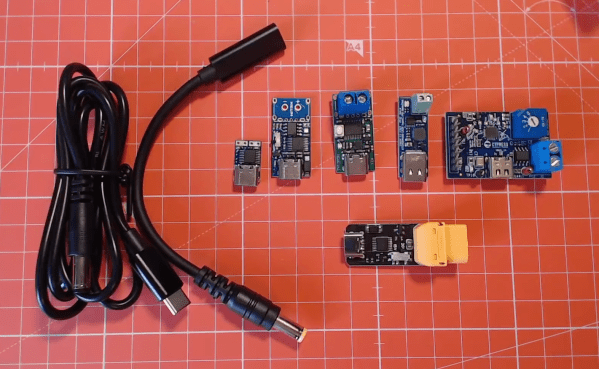
[Brian] starts off with a sorely-needed explainer of what the heck Power Delivery is; a topic with an unfortunate amount of depth. But the main goal of the video is to dive into the inscrutable hoard of “USB C trigger boards.” Typically these take USB on one side and provide a terminal block on the other, possibly with a button or LED as user interface to select voltage and current. We’ve seen these before as laptop barrel jack replacements and TS100 power supplies but it’s hard to tell which of the seemingly-identical selection is most suitable for a project.

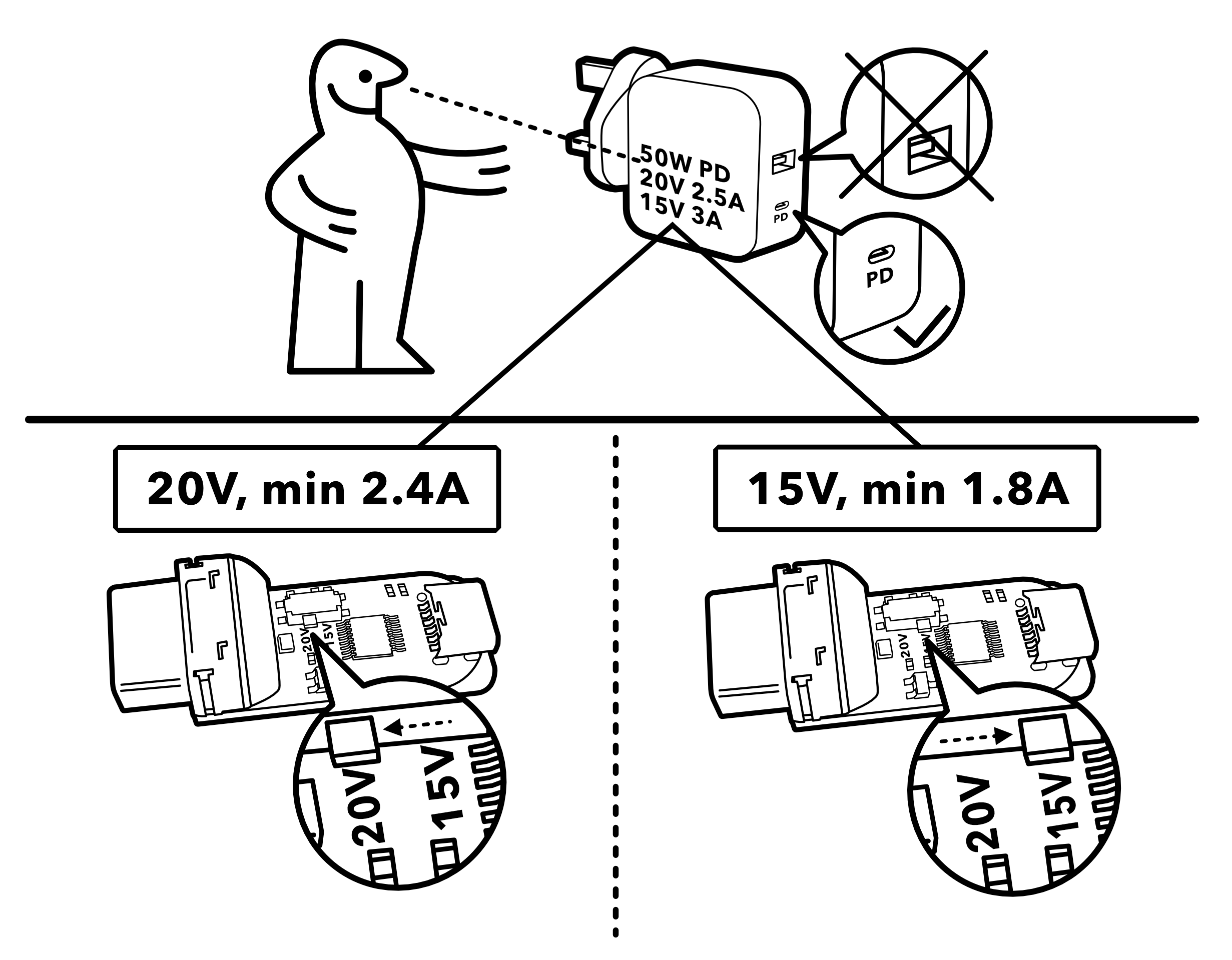
The main body of the video is [Brian’s] detailed walkthrough of four types of trigger boards, based on the IP2721, FUSB302, STUSB4500, and Cypress EZ-PD BCR. For each he describes the behaviors of it’s particular IC and how to configure it. His focus is on building a board to power a TS100 (which parallels his TS100 Flex-C-Friend) but the content is generally applicable. Of course we also appreciate his overview of the products on Tindie for each described module.

For another angle on Power Delivery, check out this series of posts by [jason cerudolo], a perennial favorite. And don’t miss his classic project, the USB Easy Bake Oven.

Even More Firmware In Your Firmware

There are many ways to update an embedded system in the field. Images can fly through the air one a time, travel by sneaker or hitch a ride on other passing data. OK, maybe that’s a stretch, but there are certainly a plethora of ways to get those sweet update bytes into a target system. How are those bytes assembled, and what are the tools that do the assembly? This is the problem I needed to solve.

Recall, my system wasn’t a particularly novel one (see the block diagram below). Just a few computers asking each other for an update over some serial busses. I had chosen to bundle the payload firmware images into the binary for the intermediate microcontroller which was to carry out the update process. The additional constraint was that the blending of the three firmware images (one carrier and two payload) needed to happen long after compile time, on a different system with a separate toolchain. There were ultimately two options that fit the bill.

The system thirsty for an update

Continue reading “Even More Firmware In Your Firmware”

Putting The Firmware In Your Firmware

Performing over-the-air updates of devices in the field can be a tricky business. Reliability and recovery is of course key, but even getting the right bits to the right storage sectors can be a challenge. Recently I’ve been working on a project which called for the design of a new pathway to update some small microcontrollers which were decidedly inconvenient.

There are many pieces to a project like this; a bootloader to perform the actual updating, a robust communication protocol, recovery pathways, a file transfer mechanism, and more. What made these micros particularly inconvenient was that they weren’t network-connected themselves, but required a hop through another intermediate controller, which itself was also not connected to the network. Predictably, the otherwise simple “file transfer” step quickly ballooned out into a complex onion of tasks to complete before the rest of the project could continue. As they say, it’s micros all the way down.

The system de jour

Continue reading “Putting The Firmware In Your Firmware”

Palm-Sized Sixteen Segments Light The Way To Our Hearts

It’s no secret that we here at the Hackaday are suckers for cool display. LEDs, OLEDs, incandescent, nixie or neon, you name it and we want to see it flash. So it fills us with joy to discover a new way to build large, daisy-chainable 16-segment digits, and even more excited to learn how easy they are to fab and assemble.

A cousin of the familiar 7 segment display, the 16 segment gives so many more possibilities (128% more possibilities to be exact) for digit display. To be specific, those extra segments unlock the ability to display upper and lowercase latin characters as well as scads of punctuation.

But where the character set is complex, the assembly is anything but thanks to a great design from [Kolibri] called klais-16. They’re available fully assembled if you want to jump straight to code, but thanks to thorough documentation (seriously, check this out) assembly is a snap.

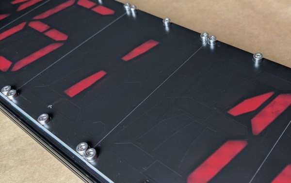
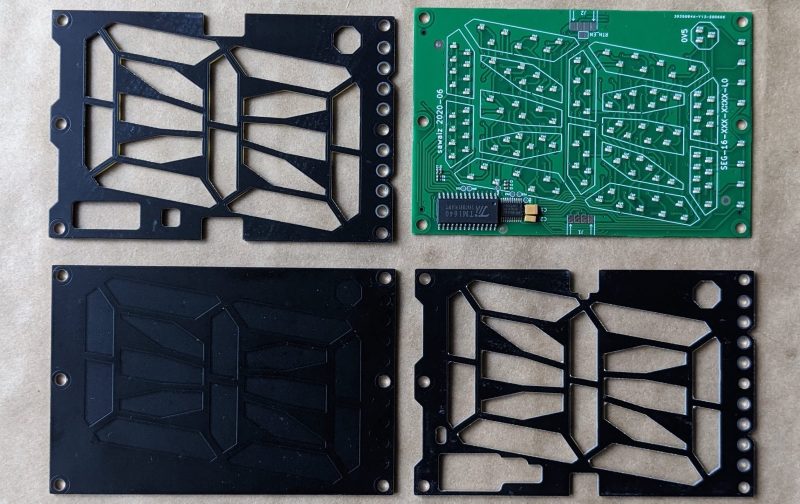
Each module is composed a very boring PCBA base layer which should be inexpensive from the usual sources, even when ordering one fully assembled. A stackup of three more PCBs are used for spacing and diffusion with plans for die-cut or injection mold layers if a larger production run ends up happening. Board dimensions for each character are 100 mm x 66.66 mm (about 4″ x 2.5″). Put together, each module can stand on its own or be easily daisy-chained together to make a longer single display.

Addressing all those bits with an elaborate, ugly control scheme would be a drag but fortunately the firmware for the onboard STM8 microcontroller exposes a nice boring serial interface which can be used without configuration to display strings. There’s even an example Windows Batch script!

Keycap Customizer Brings All Your Caps To The Board

With bright colors and often intricate designs, after the physical shape of a keyboard the most conspicuous elements are surely the keycaps. Historically dictated by the stem of the key switch it attaches to, keycaps come in a variety of sizes, colors, profiles, and designs. As they necessarily include small features with tight tolerances to fit the stem of their key switch, injection molding is the classic manufacturing technique for a keycap. But as hobbyist 3D printing matures and resin printers become more accessible, home keycap manufacturing is increasingly good option. Instead of designing each cap by hand, consider trying [rsheldiii]’s KeyV2 OpenSCAD script to create custom caps with ease.

To cover the basics, KeyV2 can generate full keycap sets with Cherry or Alps stems, in the SA, DSA, DCS profiles (and more!) for any typically sized keyboard. Generating a particular cap of arbitrary profile, position, and size is just a short chain of function calls away. But standard keycap sets aren’t the highlight of this toolset.

If you’re not an OpenSCAD aficionado yet, visit [Brian Benchoffs] great getting-started guide or our other coverage to get a feel for what the tool can do. Part of OpenSCAD’s attraction is that it is the the paragon of parametric modeling. It’s declarative part files ensure that no parameter goes undefined, which is a perfect fit for KeyV2.

The root file upon which all caps are based on has about 150 keycap parameters which can be tweaked, and that’s before more elaborate customization. Making simple “artisan” caps is a snap, as the magic of OpenSCAD means the user can perform any Boolean operations they need on top of the fully parameterized keycap. Combining an arbitrary model with a keycap is one union() away. See the README for examples.

For the prospective user of KeyV2 worried about complexity; don’t be, the documentation is a treat. Basic use to generate standard keycaps is simple, and there are plenty of commented source files and examples to make more complex usage easy. Thinking about a new keyboard? Check out our recent spike in clacky coverage.

Split Keyboard Finder Stacks Them Up For Your Approval

Tired of a boring, single piece keyboard? Thinking about a change but don’t know what all your options are? Well prospective-keyboard-shopper, today is your lucky day. We at the Hackaday are here to facilitate the habit with two excellent resources for the eager keyboard shopper; [pvinis]’s awesome-split-keyboards and [jhelvy]’s splitkbcompare.

As indicated by its title, awesome-split-keyboards is an awesome list of split keyboards 50 examples strong. Every split we’ve come across seems to be represented here, many with at least an image or two along with links to more information about how to build or buy the model in question. If that’s not enough, the bottom of the page has a wealth of background information about building or buying your own.

But before making such an important decision it’s important to make sure the keyboard in question will be a good fit in the hands. This is where splitkbcompare comes in, providing a visualization of many popular split layouts. If we hadn’t just found awesome-split-keyboards this filterable list and wide selection would have been the highlight here. But what does stand out is the ability to generate 1:1 scale printouts of the layouts in question, even stacking them for comparison, allowing a prospective buyer get a hands on feel for what they’re considering.

Not enough clackin’ action? Recently we’ve been producing a fierce amount of keyboard related content, of particular highlight is [Kristina Panos’]’ series called Inputs of Interest. Earlier in the summer she even built her own Ergodox split keeb.

[Main image source: HeliDox by diimdeep]

Playing The Pixelflut

Every hacker gathering needs as many pixels as its hackers can get their hands on. Get a group together and you’ll be blinded by the amount of light on display. (We propose “a blinkenlights” as the taxonomic name for such a group.) At a large gathering, what better way to show of your elite hacking ability than a “competition” over who can paint an LED canvas the best? Enter Pixelflut, the multiplayer drawing canvas.

Pixelflut has been around since at least 2012, but it came to this author’s attention after editor [Jenny List] noted it in her review of SHA 2017. What was that beguiling display behind the central bar? It turns out it was a display driven by a server running Pixelflut. A Pixelflut server exposes a display which can be drawn on by sending commands over the network in an extremely simple protocol. There are just four ASCII commands supported by every server — essentially get pixel, set pixel, screen size, and help — so implementing either a client or server is a snap, and that’s sort of the point.

While the original implementations appear to be written by [defnull] at the link at the top, in some sense Pixelflut is more of a common protocol than an implementation. In a sense, one “plays” one of a variety of Pixelflut minigames. When there is a display in a shared space the game is who can control the most area by drawing the fastest, either by being clever or by consuming as much bandwidth as possible.

Then there is the game of who can write the fastest more battle-hardened server possible in order to handle all that traffic without collapsing. To give a sense of scale, one installation at 36c3 reported that a truly gargantuan 0.5 petabytes of data were spent at a peak of rate of more than 30 gigabits/second, just painting pixels! That’s bound to bog down all but the most lithe server implementation. (“Flut” is “flood” in German.)

While hacker camps may be on pause for the foreseeable future, writing a performant Pixelflut client or server seems like an excellent way to sharpen one’s skills while we wait for their return. For a video example check out the embed after the break. Have a favorite implementation? Tell us about it in the comments!

Continue reading “Playing The Pixelflut”