A Tiny LED Matrix Is Better With Friends

When we last heard from [lixielabs] he was building Nixie tube replacements out of etched acrylic and LEDs. Well he’s moved forward a few decades to bring us the Pixie, a chainable, addressable backpack for tiny LED matrix displays.

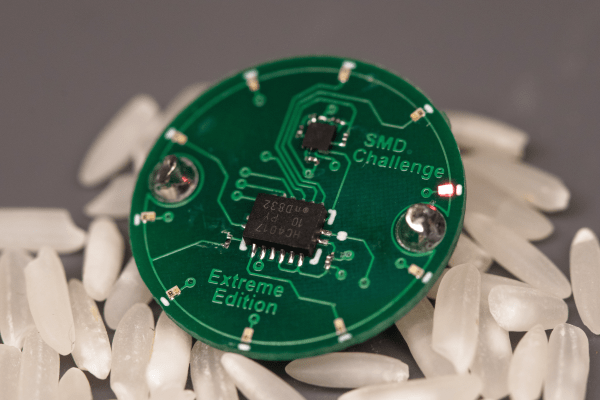
Each Pixie module is designed to host two gorgeous little Lite-On LTP-305G/HR 5×7 LED dot matrix displays, which we suspect have been impulse purchases in many a shopping cart. Along with the displays there is a small matrix controller and an ATTINY45 to expose a friendly electrical interface. Each module is designed to be mounted edge to edge and daisy chained out to 12 or more (with two displays each) for a flexible display any size you need. But to address the entire array only two control pins are required (data and clock).

[lixielabs] has done the legwork to make using those pins as easy as possible. He is careful to point out the importance of a good SDK and provides handy Arduino libraries for common microcontrollers and a reference implementation for the Raspberry Pi that should be easy to crib from to support new platforms. To go with that library support is superb documentation in the form of a datasheet (complete with dimensions and schematic!) and well stocked GitHub repo with examples and more.

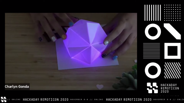
To get a sense of their graphical capabilities, check out a video of 6 Pixie’s acting as a VU meter after the break. The Pixie looks like what you get when a hacker gets frustrated at reinventing LED dot matrix control for every project and decided to solve it once and for all. The design is clean, well documented, and extremely functional. We’re excited to see what comes next! Continue reading “A Tiny LED Matrix Is Better With Friends”

Remoticon Video: Making Glowy Origami With Charlyn Gonda

Hacking is about pushing the envelope to discover new and clever ways to use things in ways their original designers never envisioned. [Charlyn Gonda]’s Hackaday Remoticon workshop “Making Glowly Origami” was exactly that; a combination of the art of origami with the one of LEDs. Check out the full course embedded below, and read on for a summary of what you’ll find. Continue reading “Remoticon Video: Making Glowy Origami With Charlyn Gonda”

Remoticon Video: How To 3D Print Onto Fabric With Billie Ruben

We’re impressed to see the continued flow of new and interesting ways to utilize 3D printing despite its years in the hacker limelight. At the 2020 Hackaday Remoticon [Billie Ruben] came to us from across the sea to demonstrate how to use 3D printing and fabric, or other flexible materials, to fabricate new and interesting creations. Check out her workshop below, and read on for more detail about what you’ll find.

The workshop is divided into two parts, a hands-on portion where participants execute a fabric print at home on their own printer, and a lecture while the printers whirr away describing ways this technique can be used to produce strong, flexible structures.

The technique described in the hands on portion can be clumsily summarized as “print a few layers, add the flexible material, then resume the printing process”. Of course the actual explanation and discussion of how to know when to insert the material, configure your slicer, and select material is significantly more complex! For the entire process make sure to follow along with [Billie]’s clear instructions in the video.

The lecture portion of the workshop was a whirlwind tour of the ways which embedded materials can be used to enhance your prints. The most glamourous examples might be printing scales, spikes, and other accoutrement for cosplay, but beyond that it has a variety of other uses both practical and fashionable. Embedded fabric can add composite strength to large structural elements, durable flexibility to a living hinge, or a substrate for new kinds of jewelry. [Billie] has deep experience in this realm and she brings it to bear in a comprehensive exposition of the possibilities. We’re looking forward to seeing a flurry of new composite prints!

These Micro Mice Have Macro Control

Few things fascinate a simple Hackaday writer as much as a tiny robot. We’ve been watching [Keri]’s utterly beguiling micromouse builds for a while now, but the fifth version of the KERISE series (machine translation) of ‘bots takes the design to new heights.

A family of mice v1 (largest) to v5 (smallest)

For context, micromouse is a competition where robots complete to solve mazes of varying pattern but standardized size by driving through them with no guidance or compute offboard of the robot itself. Historically the mazes were 3 meter squares composed of a 16 x 16 grid of cells, each 180mm on a side and 50mm tall, which puts bounds on the size of the robots involved.

What are the hallmarks of a [Keri] micromouse design? Well this is micromouse, so everything is pretty small. But [Keri]’s attention to detail in forming miniaturized mechanisms and 3D structures out of PCBs really stands out. They’ve been building micromouse robots since 2016, testing new design features with each iteration. Versions three and four had a wild suction fan to improve traction for faster maneuvering, but the KERISE v5 removes this to emphasize light weight and small size. The resulting vehicle is a shocking 30mm x 32mm! We’re following along through a translation to English, but we gather that [Keri] feels that there is still plenty of space on the main PCBA now that the fan is gone.

The KERISE v5 front end

The processor is a now familiar ESP32-PICO-D4, though the wireless radios are unused so far. As far as environmental sensing is concerned the v5 has an impressive compliment given its micro size. For position sensing there are custom magnetic encoders and a 3 DOF IMU. And for sensing the maze there are four side-looking IR emitter/receiver pairs and one forward-looking VL6180X laser rangefinder for measurements out to 100 or 150mm. Most of these sensors are mounted on little PCB ‘blades’ which are double sided (check out how the PCB shields the IR emitter from it’s receiver!) and soldered into slots perpendicular to the PCBA that makes up the main chassis. It goes without saying that the rest of the frame is built up of custom 3D printed parts and gearboxes.

If you’d like to build a KERISE yourself, [Keri] has what looks to be complete mechanical, electrical, and firmware sources for v1, v2, and v3 on their Github. To see the KERISE v5 dance on a spinning sheet of paper, check out the video after the break. You don’t want to miss it!

Continue reading “These Micro Mice Have Macro Control”

Templateize Your Timetable With EPaper Templates

To date, e-paper technology has been great for two things, displaying static black and white text and luring hackers with the promise of a display that is easy on the eyes and runs forever. But poor availability of bare panels has made the second (we would say more important) goal slow to materialize. One of the first projects that comes to mind is using such a display to show ambient information like a daily summary weather, train schedules, and calendar appointments. Usually this means rolling your own software stack, but [Christopher Mullins] has put together a shockingly complete toolset for designing and updating such parameterized displays called epaper_templates.

To get it out of the way first, there is no hardware component to epaper_templates. It presupposes you have an ESP32 and a display chosen from a certain list of supported models. A quick search on our favorite import site turned up a wide variety of options for bare panels and prebuilt devices (ESP32 and display, plus other goodies) starting at around $40 USD, so this should be a low threshold to cross.

Once you have the device, epaper_templates provides the magic. [Christopher]’s key insight is that an ambient display is typically composed of groups of semi-static data displayed in a layout that never changes. The only variation is updates to the data which is fully parameterized: temperature is always integer Fahrenheit, train schedules are lists of minutes and hours, etc. Layouts like this aren’t difficult to make, but require the developer to reimplement lots of boilerplate. To make them easy to generate, epaper_templates provides a fully featured web UI to let the user freely customize a layout, then exports it as JSON which the device consumes.

The sample layout configured in the video below

The web UI is shockingly capable, especially for by the standards of the embedded web. (Remember it’s hosted on the ESP32 itself!) The user can place text and configure fonts and styles. Once placed, the text can be set to static strings or tied to variables, and if the string is a timestamp it can be formatted with a standard strftime format string.

To round out the feature set, the user can place images and lines to divide the display. Once the display is described, everything becomes simple to programmatically update. The ESP can be configured to subscribe to certain MQTT topics from which it will receive updates, or if that is too much infrastructure there is a handy REST API which accepts JSON objects containing variables or bitmaps to update on device.

We’re totally blown away by the level of functionality in epaper_templates! Check out the repo for more detail about its capabilities. For a full demo which walks through configuration of a UI with train arrival times, weather, both instant temperature and forecast with icons, and date/time check out the video after the break. Source for the example is here, but be sure to check out examples/ in the repo for more examples.

Continue reading “Templateize Your Timetable With EPaper Templates”

This Debug Connector Brings Your Issues To The Edge

Given an unknown PCBA with an ARM processor, odds are good that it will have either the standard 10 pin 0.05″ or 20 pin 0.1″ debug connector. This uncommon commonality is a boon for an exploring hacker, but when designing a board such headers require board space in the design and more components to be installed to plug in. The literally-named Debug Edge standard is a new libre attempt to remedy this inconvenience.

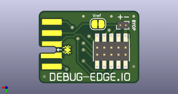
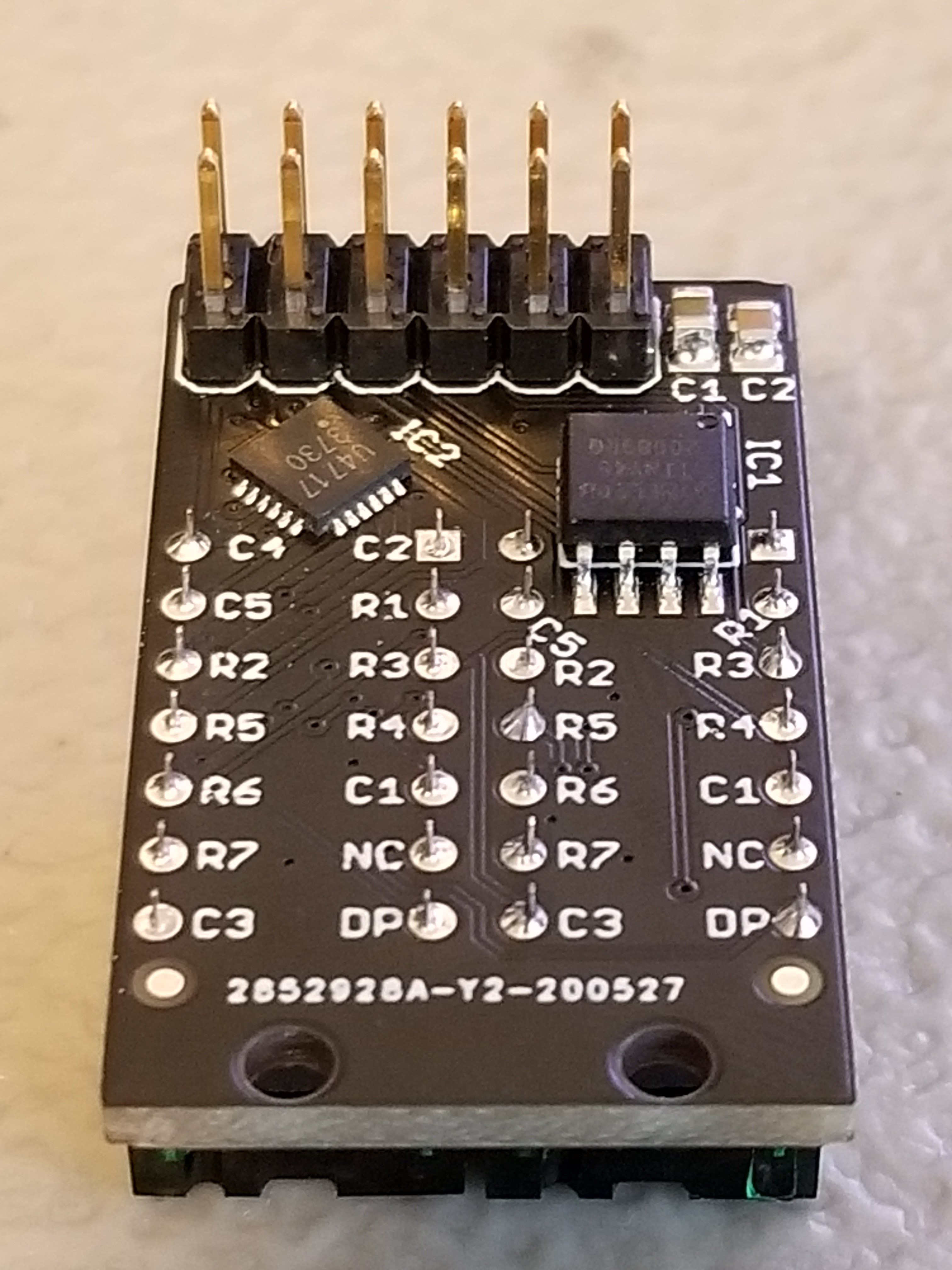
The name “Debug Edge” says it all. It’s a debug, edge connector. A connector for the edge of a PCBA to break out debug signals. Card edge connectors are nothing new but they typically either slot one PCBA perpendicularly into another (as in a PCI card) or hold them in parallel (as in a mini PCIe card or an m.2 SSD). The DebugEdge connector is more like a PCBA butt splice.

It makes use of a specific family of AVX open ended card edge connectors designed to splice together long rectangular PCBAs used for lighting end to end. These are available in single quantities starting as low as $0.85 (part number for the design shown here is 009159010061916). The vision of the DebugEdge standard is that this connector is exposed along the edge of the target device, then “spliced” into the debug connector for target power and debug.

Right now the DebugEdge exists primarily as a standard, a set of KiCAD footprints, and prototype adapter boards on OSHPark (debugger side, target side). A device making use of it would integrate the target side and the developer would use the debugger side to connect. The standard specifies 4, 6, 8, and 10 pin varieties (mapping to sizes of available connector, the ‘010’ in the number above specifies pincount) offering increasing levels of connectivity up to a complete 1:1 mapping of the standard 10 pin ARM connector. Keep in mind the connectors are double sided, so the 4 pin version is a miniscule 4mm x 4.5mm! We’re excited to see that worm its way into a tiny project or two.

We’ve seen plenty of part-free debug and programming connectors before. Have a favorite? Let us know in the comments!

SMD Challenge Extreme Edition Gets Our Flux Flowing

Skills challenges have become a fun way to facilitate friendly competition amongst anyone who appreciates a fine solder joint. If you’ve seen any Supercon / Remoticon coverage there’s surely been a mention of the infamous soldering skills challenge, where competitors test their mettle against surface mount components sized to be challenging but fair. What if there was a less friendly SMD challenge designed to make you hold your breath lest you blow the components away? Well now there is, the SMD Challenge Extreme Edition by friend-of-the-Hackaday and winner of the 2019 Supercon soldering challenge [Freddie].

When assembled the SMD Extreme Edition uses a 555 timer and a 74HC4017 decade counter to light a ring of 10 LEDs lights around its perimeter, powered by a coin cell. However the  Extreme Edition deviates from the typical SMD Challenge format. Instead of ramping up in difficulty with ever-shrinking components, the Extreme Edition only has one size: torturous. See those gray blobs in the title image? Those are grains of rice.

The Extreme Edition’s 0201-sized LEDs aren’t the absolute smallest components around, but to minimize enjoyment all passives are 01005. (Check out the SMD Challange Misery Edition for even 01005 LED action.)

The Extreme Edition has other tricks up its sleeve, too. That 555 may be venerable in age, but this version is in an iron-frustrating 1.41 x 1.43 mm BGA package, which pairs nicely with that decade counter in 2.5 mm x 3.5 mm QFN.

Despite the wordwide pandemic locking down travel and conferences, a few brave challengers have already taken up their iron and succeeded at Extreme SMD. Want to see it in action? Check out the original Tweets after the break.

Continue reading “SMD Challenge Extreme Edition Gets Our Flux Flowing”