KiCad Video Series: From Concept To Manufacture

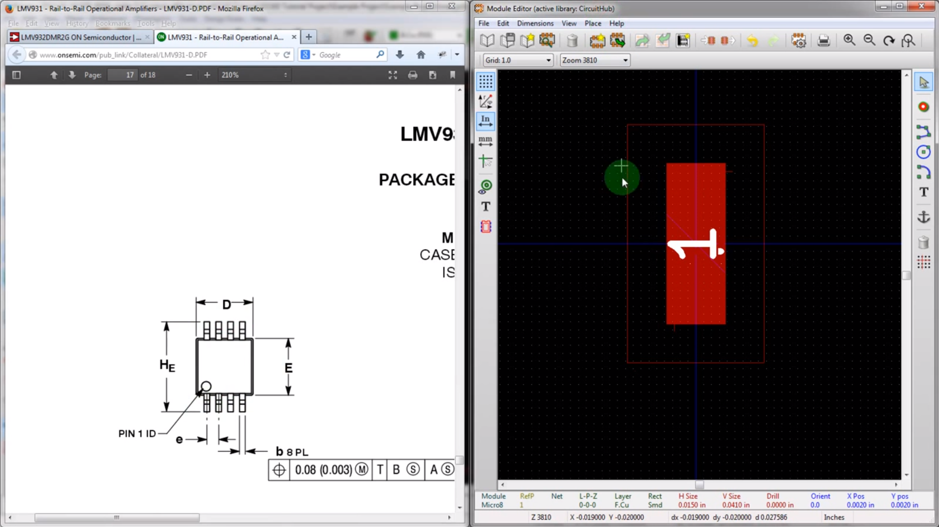
Many of our readers took the habit of using Eagle to design their PCBs. Even if you’ll find plenty of support for this software as well as a lot of parts libraries, the software comes with limitations. The useable board area is limited to 4×3.2 inches, only two signal layers can be used and more importantly the schematics editor can only create one sheet. On the other side, some of you may already know KiCad, a free open source and unrestricted schematics and layout software. [Chris] just tipped us of a video series he made, showing people how to design and build their very first PCB using this software. It’s a simple 555 circuit, but goes through all the steps necessary to design a PCB that costs only $5 through OSHpark… and will blink by the end. All the videos are also embedded after the break.

Continue reading “KiCad Video Series: From Concept To Manufacture”

Wireless Encryption Between Galileo And A MSP430

[Mark] recently finished his latest project, where he encrypts wireless communications between the new Intel Galileo and a Texas Instruments MSP430. The wireless interfaces used are the very common nRF24L01+ 2.4GHz transceivers, that had a direct line of sight 15 feet range during [Mark]’s tests. In his demonstration, the MSP430 sends an encrypted block of data representing the state of six of its pins configured as inputs. This message is then received by a sketch running on the Galileo and stored in shared memory. A python script then wakes up and is in charge of decrypting the message. The encryption is done using AES-128bits in Electronic Codebook mode (ECB) and semaphores are used to prevent simultaneous accesses to the received data. As it is the first project using an Intel Galileo we received, don’t hesitate to send us a tip if you found other ones.

A Cortex M4 Based Platform With ETH, USB, BT And Many On-board Peripherals

Here is a very time consuming project that I worked on during last summer: an ARM Cortex M4 based platform with plenty of communication interfaces and on-board peripherals. The particular project for which this board has been developed is not really HaD material (one of my father’s funny ideas) so I’ll only describe the platform itself. The microcontroller used in the project is the ATSAM4E16C from Atmel, which has 1Mbyte of flash and 128Kbytes of SRAM. It integrates an Ethernet MAC, a USB 2.0 Full-speed controller, a sophisticated Analog to Digital Converter and a Digital to Analog Converter (among others).

Here is a list of the different components present on the board so you can get a better idea of what the platform can do: a microphone with its amplifier, a capacitive touch sensor, two unipolar stepper motors controllers, two mosfets, a microSD card connector, a Bluetooth to serial bridge, a linear motor controller and finally a battery retainer for backup power. You can have a look at a simple demonstration video I made, embedded after the break. The firmware was made in C and uses the Atmel Software Framework. The project is obviously open hardware (Kicad) and open software.

Continue reading “A Cortex M4 Based Platform With ETH, USB, BT And Many On-board Peripherals”

Hacking A Flip Dot Display

While casually lurking on a famous auction website, [TeddyDesTodes] found the gem shown in the above picture and reverse engineered it. This is a flip dot display, the Brose Vollmatrix compact to be precise. It consists of a grid of small metal discs that are black on one side and yellow on the other, set into a black background. With power applied, the disc flips to show the other side. The disc is attached to an axle which also carries a small permanent magnet. Positioned close to the magnet is a solenoid. By pulsing the solenoid coil with the appropriate electrical polarity, the magnet will align itself with the magnetic field, also turning the disc.

After carrying the 25kg display from his post office to home, [TeddyDesTodes] opened it and discovered that the main control board was using two RS422 transceivers. So he fired up his bus pirate, started to sniff the traffic and noticed that several commands were repeatedly sent. [TeddyDesTodes] stopped the transmission, sent these particular commands and had the good surprise to see some dots flipped. From there, displaying something was a piece of cake.

If this is familiar to you it may be because it was shared in one of the Trinket Contest Updates. But the background details were just so much fun we think this deserves a full feature of it’s own. Do you agree?

Making A Solid-state Relay With I2C Interface

As [Mic] often got requests to make high-power switching boards, he recently finally gave in and designed the one shown above based around a solid-state relay. Some of our readers that already play with mains power know that switching should normally occur when the voltage crosses zero volts. The ‘TRIAC BLOC’ is able to do so, which also allows mains frequency measurement. [Mic] then tuned to the internal oscillator of his ATtiny microcontroller with this 50Hz by adjusting its OSCCAL register value, so the switching command can be sent at the ideal moment. Zero crossing detection is implemented by feeding the mains into an AC optocoupler. [Mic] discovered that the optocoupler diodes are not identical, so he had to adjust his firmware to account for the time differences.

All the resources are available on github, we would be interested to hear your detailed analysis of the circuit implemented with the passives R3/C1/L1/R8/C3.

Hackaday Interview With Amal Graafstra, Creator Of XNT Implant Chip

Near Field Communication (NFC) enabled devices are starting to appear in our everyday lives. Shown in the picture above is the xNT (fundraiser warning), a 2mm x 12mm fully NFC Type 2 compliant 13.56MHz RFID tag encased in a cylindrical Schott 8625 bioglass ampule. It was created by [Amal Graafstra], who therefore aims to produce the world’s first NFC compliant RFID implant. The chip used is the NTAG203, which is (for the sake of simplicity) a 144bytes EEPROM with different protection features.

We can only start thinking of the different possibilities this chip will create in the near future, but also wonder which precedent this may set for future NFC enabled humans. Embedded after the break is the presentation video of xNT but also an interview I conducted with [Amal Graafstra], who has already been living for 8 years with RFID tags in each hand.

Continue reading “Hackaday Interview With Amal Graafstra, Creator Of XNT Implant Chip”

Building A DC Constant Current/Power Electric Load

By just looking at the picture above, we’re pretty sure that most Hackaday readers will have guessed by now that much power can be dissipated by this electric load. For those who don’t know, an electric load (or dummy load) is a device used to simulate a load on a system for testing purposes. This is quite handy when measuring battery capacities or testing power supplies.

The heart of the device that [Kerry] designed is based on 6 power MOSFETs, a few operational amplifiers and an Arduino compatible ATmega328p microcontroller. Sense resistors are used to measure how much current is passing through the MOSFETs (and therefore the load), the MCP4921 Digital to Analog Converter (DAC) from microchip is used to set the current command, and the load’s voltage is measured by the ATmega ADC. Measuring the latter allows a constant power load mode (as power = current * voltage). In his article, [Kerry] shows that he can simulate a load of up to 200W.

Continue reading “Building A DC Constant Current/Power Electric Load”