Sending Data Over Bluetooth Low Energy With A Cheap NRF24L01+ Module

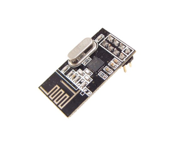
nRF24L01+ modules like the one shown above are a great way to send data wirelessly between your projects. They can be found on many websites for less than $1.50 a piece and many libraries exist for them. After having thoroughly looked at the Bluetooth Low Energy (BLE) specifications, [Dimitry] managed to find a way to broadcast BLE data with an nRF24L01+.

Luckily enough, BLE and nRF24L01+ data packets have the same preambles. However, the latter can’t send more than 32 bytes in a packet and can’t hop between frequencies as fast as the BLE specification wants. [Dimitry] found the solution when he discovered that he could send unsolicited advertisements on three specific channels. In the end, considering the 32 bytes the nRF24L01+ can send, you’ll need to use 3 bytes for the CRC, 2 for the packet header, 6 for the MAC address and 5 for devices attributes. This leaves us with 16 bytes of pure data or 14 bytes to split between data and name if you want your project to have one.

Accurate Temperature Control Of Your 3D Printer Extruder

[Tim] is working on building a 3D printer and using it as an excuse to learn as much as he can. The first big issue he tackled was accurate temperature control, so he made an interesting write-up on how to characterize the thermal properties of an QU-BD extruder’s hot end and use that information to create a control algorithm for the heater.

The article starts with a basic thermal model and its corresponding formula. [Tim] then runs several tests where he measures the heater and extruder tip temperatures while switching on and off the heater. This allows him to figure out the several model parameters required to design his control algorithm. Finally, he tweaked his formula in order to predict the short term future so he can know when he should activate the heating element. As a result, his temperature is now accurately controlled in the 200°c +/-1°c window that he was shooting for.

Explaining The Low Level Stuff You Don’t Know About ARM Programming

Most of us don’t realize how spoiled we are with the different development environments available on the internet. If someone wants to start a blank project on a new [ARM/DSP/…] platform, he usually fires up the dedicated Integrated Development Environment (IDE) and starts coding a C/C++ program. However, there are many initialization routines and scripts required with your program before it can run correctly. In his great article, [Andrew] explains to us what these are by starting a blank project without using any IDE.

As you can see in the above picture, [Andrew]’s project is made around an Atmel SAM4E microcontroller. The chosen toolchain is the arm-none-eabi-gcc from GNU Tools for ARM Embedded Processors. The first part of the article starts with a simplified explanation on how/why your code and variables are split into different memory sections (.bss, .data, .rodata, .text), then [Andrew] details how the linker script will put these sections at different physical addresses depending on your microcontroller’s memory layout. He also shows us how to take care of the stack placement, vector table, variable (non)initialization, and C Runtime. For information, the latter is executed when your processor starts, it is in charge of setting up the stack pointer, initializing the RAM, setting up the standard library and calling the main().

A very nice introduction on the very low level routines running on most processors out there.

Update: McHck’s Self Flashing Rig

A few weeks ago we featured the McHck project (pronounced McHack), a $5 Cortex M4 based platform which can be directly plugged into one’s computer. Recently, [Simon] announced that he made a firmware allowing a McHck to behave as a SWD adapter and also detailed his flashing rig.

Therefore, those who’d want to build their own McHck would only need to borrow an SWD programmer once to get started. When the first platform has been programmed with the SWD firmware, it can be used to flash and debug applications on the second McHck. Consequently, the microcontroller flashing rig [Simon] designed (shown in the picture above) is based on this. The few core elements are a TQFP48 ZIF programming socket, a push button and two LEDs. Simply push the Kinetis in the programming socket, close it and press the button. Success of the operation is indicated by the two LEDs. [Simon] used the Ragel State Machine Compiler to generate his flashing program and all the code he made can be downloaded from his github.

If you missed the original McHck post now’s your chance to go back and see what it is all about.

Cloning An Infrared Disarming Remote Of A $8 Home Security System

5

[Sylvio] decided to buy one of the cheap alarm systems you can find on the internet to have a look at its insides. The kit he bought was composed of one main motion sensor and two remote controls to arm/disarm it.

Communication between the remotes and the sensor is done by using infrared, requiring a direct line of sight for a signal to be received. Modern alarm systems typically use RF remotes with a typical frequency of 434MHz or 868MHz.  In his write-up, [Sylvio] first tries to replicate the IR signal with one of his ‘learning remote controls’ without success and then proceed to reverse engineering the remote circuit shown in the above picture. Hackaday readers may figure out just by looking at it that it is a simple astable multivibrator (read ‘oscillator’). Its main frequency is 38.5kHz, which is typical for IR applications. Therefore, if one of your neighbours had this ‘security system’ one could just disarm it with any of the same remotes…

[Sylvio] then explains different ways to replicate the simple IR signal, first with an Arduino then with a frequency generator and finally using the USB Infrared Toy from Dangerous Prototypes. We agree with his conclusion: “you get what you pay for”.

A 23 Feet Tall Pyramid With 0.31 Mile Of LED Strips

This year the Disorient Camp at Burning Man built a 7m tall pyramid with over half a kilometer of LED strips. For this special occasion several artists had developed patterns for this massive LED display, animating the parties happening every night in front of this build.

To handle the dusty environment, a Toughbook was running the pyramid’s main code, which was rendering the animation frames to 24-bit bitmaps and sending them over UDP to the network. For each face of the pyramid, a $45 BeagleBone Black running a dedicated program was slicing the images into the individual panels. Finally, each panel composed of eight WS281x LED strips was driven by a Teensy 3.0 microcontroller, receiving the piece to display by USB from the BeagleBone. To power the pyramid, 5V 40A power supplies were used for the tall panels, 5V 30A power supplies for the smaller ones.

Unsurprisingly, many of the power supplies failed due to the heat and dust.  The adhesive holding the LED strips also failed, and some screw terminals rattled loose from the 25KW sound system, requiring constant maintenance. Nevertheless, the sixteen thousand LEDs sure made quite an impression.

If anyone attending Burning Man managed to capture video of this thing in action we’d love to see it. Leave a link in the comments.