Another Take On Harvesting Energy While Walking

Harvesting energy from the human body may sound scary, but fortunately a Matrix-style setup exists only as a cinematic fiction. Instead a typical path lies in external contraptions that use the body’s natural motions to drive a small generator, a bit of flexible piezo material, and so on. A popular target for harvesting the body’s kinetic energy is the knee joint, as this has a comparatively large range of motion and is fairly easy to use.

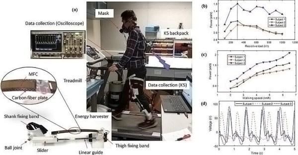
Thus a team from Hong Kong university opted to pick this part of the human anatomy for their experiment as well. While at first glance their results do not seem particularly impressive, with up to 1.6 mW of power generated, a look at their published results in the Applied Physics Letters journal showed their reasoning behind this setup. While one generator-based setup referenced produces on average 4.8 Watt of power, the device itself weighs 1.6 kg and increases the rate at which the person wearing it burns calories by a significant amount.

The goal for this device was to have a way to generate significant amounts of power without having the user exerting themselves more than usual. This led to them using flexible piezoelectric composites, resulting in a weight of just 307 grams, based upon two M8514-P2 pieces (Smart Materials Corp. manufacturer). Tests with volunteers on a treadmill show that users do not burn more calories than without.

As with all piezo materials, they can flex a bit, but not too much, so a lot of time and effort went into calculating the optimal bend radius in different usage scenarios. While around 1 mW of power is not massive, it is a reliable source of power for individuals who do any amount of walking during the day and doesn’t require any effort beyond strapping the device onto one’s legs.

Pushing Pixels To A Display With VGA Without A PC

[Ben Eater] is back with the second part of his video series on building a simple video card that can output 200×600 pixels to a display with nothing but a VGA connection, a handful of 74-logic chips and a 10 MHz crystal. In this installment we see how he uses nothing but an EEPROM and a handful of resistors to get an image onto the screen.

The interesting part is in how the image data is encoded into the EEPROM, since it has to be addressable by the same timing circuit as what is being used for the horizontal and vertical timing. By selecting the relevant inputs that’d make a valid address, and by doubling the size of each pixel a few times, a 100 x 75 pixel image can be encoded into the EEPROM and directly addressed using this timing circuit.

The output from the EEPROM itself not fed directly into the monitor, as the VGA interface expects a 0 V to 0.7 V signal on each RGB pin, indicating the brightness. To get more than three colors out of this setup, [Ben] builds up a simple 2-bit DAC that allows for two bits per channel, meaning four brightness levels per color channel or 64 colors effectively.

See the video after the link for the full details. While pretty close to perfect, a small issue remains at the end in the forms of black vertical lines. These are caused by a timing issue in the circuit, with comments on the YouTube video suggesting various other potential fixes. Have you breadboarded your own version yet to debug this issue before [Ben]’s next video comes out?
Continue reading “Pushing Pixels To A Display With VGA Without A PC”

Exploring The Raspberry Pi 4 USB-C Issue In-Depth

It would be fair to say that the Raspberry Pi team hasn’t been without its share of hardware issues, with the Raspberry Pi 2 being camera shy, the Raspberry Pi PoE HAT suffering from a rather embarrassing USB power issue, and now the all-new Raspberry Pi 4 is the first to have USB-C power delivery, but it doesn’t do USB-C very well unless you go for a ‘dumb’ cable.

Join me below for a brief recap of those previous issues, and an in-depth summary of USB-C, the differences between regular and electronically marked (e-marked) cables, and why detection logic might be making your brand-new Raspberry Pi 4 look like an analogue set of headphones to the power delivery hardware.

Continue reading “Exploring The Raspberry Pi 4 USB-C Issue In-Depth”

Building A Development Board For The STM32 G0 Series

When [Andy Brown] recently tripped over ST’s new G0 series of MCUs, he figured after some research that the best way to learn everything there’s to know about the STM32G0xx by making his own development board based around the STM32G081. The result is a Nucleo-style board, breaking out all pins to convenient 2.54 mm headers, and with a number of niceties, such as an on-board coin cell and 32.768 kHz LSE oscillator for RTC use and three different power supplies (3.3 V, 2.5 V, and 1.8 V) for the MCU.

The board is programmed with an external ST-Link programmer that connects to the SWD interface on the MCU, with a 20-pin programming header provided. While by no means small or compact, it makes for very easy breadboarding and prototyping, with all 2.54 mm headers accessible from the bottom and top.

As for the STM32G0 series itself, the jury is still out on its performance compared to the F0. The former swaps the Cortex-M0 core for an M0+, with a reduced pipeline length (3 stages in the G0) but increased frequency (64 MHz versus 48 MHz). The G0 has a little bit more SRAM, but so far less Flash storage. According to ARM, this MCU range is designed to remove any need to still use an 8-bit MCU. Big claims, indeed.

The biggest issue which [Andy] had while developing this board was probably with the CH340 USB-UART chip. Ordering them from AliExpress as is common, the CH340G ICs he got just wouldn’t work on the first board revision, forcing him to switch to the CH340E and requiring a board respin. This version has an internal oscillator and as a bonus even came in the original tape packaging when it arrived, instead of in a plastic baggy like with the CH340G parts.

See a video of [Andy] going through the design after the break.

Continue reading “Building A Development Board For The STM32 G0 Series”

Using Super-Efficient Solar Cells To Keep Your Electric Car’s Battery Topped Up

Who hasn’t thought of sticking a couple of solar panels onto an electric car’s roof to keep its battery at 100% charge while it’s parked out in the sun? While usually deemed impossible due to the large number and weight of PV solar cells required to get the necessary amount of energy, this hasn’t kept Toyota’s engineers from covering one of their Prius cars with 34+% efficient solar cells.

Some may remember the solar roof option which Toyota previously offered years ago. That system produced a mere 50 W and was only used for things like running the AC fans, indirectly extending the battery charge. In 2016 Toyota brought back this system, in a much improved version. This upped the power output to 180 W, allowing it to power all secondary electronics in the Prius, even allowing it to add a few extra kilometers (roughly 6.1 km/day) to the Prius’ range if one were so inclined.

This newest prototype pretty much goes for broke, reminding us of the cars used in the World Solar Challenge, such as the Dutch Stella and Stella Lux positive-energy solar cars by the team at the University of Eindhoven. Who coincidentally have done a spin-off, setting up a company to produce the Lightyear One, which at least on paper sounds amazing, and potentially may never have to plug it in.

Continue reading “Using Super-Efficient Solar Cells To Keep Your Electric Car’s Battery Topped Up”

Safely Measuring Single And Three-Phase Power

There are many reasons why one would want to measure voltage and current in a project, some applications requiring one to measure mains and even three-phase voltage to analyze the characteristics of a device under test, or in a production environment. This led [Michael Klopfer] at the University of California, Irvine along with a group of students to develop a fully isolated board to analyze both single and three-phase mains systems.

Each of these boards consists out of two sections: one is the high-voltage side, with the single phase board using the Analog Devices ADE7953 and the three-phase board the ADE9708. The other side is the low-voltage, isolated side to which the microcontroller or equivalent connects to using either SPI or I2C. Each board type comes in either SPI or I2C flavor.

Each board can be used to measure line voltage and current, and the Analog Devices IC calculates active, reactive, and apparent energy, as well as instantaneous RMS voltage and current. All of this data can then be read out using the provided software for the Arduino platform.

The goal of this project is to make it easy for anyone to reproduce their efforts, with board schematics (in Eagle format) and the aforementioned software libraries provided. Here it is somewhat unfortunate that the documentation can be somewhat incomplete, with basic information such as input and measurement ranges missing. Hopefully this will improve over the coming months as it does seem like a genuinely useful project for the community.

We’ve covered the work coming out of [Michael]’s lab before, including this great rundown on Lattice FPGAs. They’re doing machine vision, work on RISC-Vchips, and more. A stroll through the lab’s GitHub is worth your time.


Understanding Elliptic Curve Cryptography And Embedded Security

We all know the usual jokes about the ‘S’ in ‘IoT’ standing for ‘Security’. It’s hardly a secret that security in embedded, networked devices (‘IoT devices’) is all too often a last-minute task that gets left to whichever intern was unfortunate enough to walk first into the office that day. Inspired by this situation, All About Circuits is publishing a series of articles on embedded security, with a strong focus on network security.

In addition to the primer article, so far they have covered the Diffie-Hellman exchange (using prime numbers, exponentiation and modular arithmetic) and the evolution of this exchange using elliptic curve cryptography (ECC) which prevents anyone from brute-forcing the key. Barring any quantum computers, naturally. All three articles should be understandable by anyone, with a simple, step-by-step format.

The upcoming articles will cover implementing security on microcontrollers specifically.  For those who cannot wait to learn more, Wikipedia has a number of articles on the topic of Elliptic Curve Cryptography (comparing it to the more older and still very common RSA encryption) specifically, as well as the Elliptic-Curve Diffie-Hellman key agreement protocol as discussed in the All About Circuits article.

A detail of note here is that the hardest problem in secure communications isn’t to keep the communications going, but to securely exchange the keys in the first place. That’s why a much much computationally expensive key exchange scheme using an asymmetric (or public-key) cryptography scheme  is generally used to set up the second part of the communications, which would use a much faster symmetric-key cryptography scheme, where both parties have the means to decode and encode messages using the same private key.

All the math aside, one does have to wonder about how one might denote ‘secure’ IoT. Somehow ‘SIoT’ doesn’t feel very catchy.