Omnirotor flies over obstacles with its gimballed, caged, coaxial rotors.

Gimballed Omnirotor Goes Over Great Obstacles

What can drive on the ground, hop in the air, and continuously move its coaxial rotor assembly without ever having to reset its position? The answer is [New Dexterity]’s Omnirotor All-Terrain Platform.

Although still very much a prototype, the video below the break shows that the dexterity claimed by Omnirotor isn’t just a lot of hype. Weaving through, around, and over obstacles is accomplished with relative ease by way of a coaxial rotor configuration that’s sure to turn some heads.

Omnirotor flies over obstacles with its gimballed, caged, coaxial rotors.
Omnirotor’s unique design lends to its agility

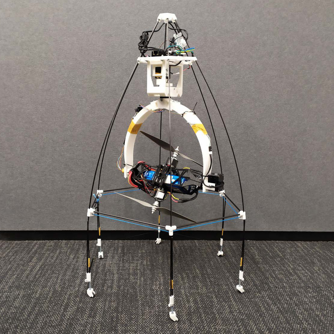
While not novel in every aspect, the Omnirotor’s strength comes from a combination of features that are fairly unique. The coaxial rotors are fully gimballed, and as such can be moved to and from any direction from any other direction. In other words, it can rotate in any axis infinitely without needing to return to a home position. Part of this magic comes from a very clever use of resources: The battery, speed controllers, and motors are all gimballed as one. This clever hack avoids the need for large, heavy slip rings that would otherwise be needed to transmit power.

Adding to the Omnirotor’s agility is a set of wheels that allow the craft to push itself along a surface, presumably to decrease power consumption. What if an obstacle is too difficult to drive around or past? The Omnirotor takes to the air and flies over it. The coaxial rotors are caged, protecting them from the typical rotor-snagging dangers you’d expect in close quarters.

[New Dexterity] has Open Sourced the entire project, with the Omirotor design, Firmware, and even the benchmarking platform available on Github so that others can share in the fun and iterate the design forward even further.

You might also enjoy this tetrahedron based omnirotor, or another omnirotor that knows how to play fetch. Really.

Continue reading “Gimballed Omnirotor Goes Over Great Obstacles”

Space Shuttle Model In A Hypersonic Wind Tunnel

Mach 20 In A Wind Tunnel: Yes, It’s Rocket Science

Hypersonic speeds are defined by those exceeding Mach 5, and lately there’s been a lot of buzz about unmanned hypersonic vehicles making test flights. Vehicles returning from orbital flight also travel at hypersonic speeds as they do their best to transition back to the terrestrial realm. Before anything leaves ground though, these machines are tested in wind tunnels. [Scott Manley]’s video “How Hypersonic Wind Tunnels Recreate Mach 20” (embedded below) does a wonderful job of explaining the engineering behind wind tunnels for testing hypersonic vehicles.

While the earliest wind tunnels such as that used by the Wright Brothers were powered by simple fans, it is not possible for any propeller to surpass subsonic speeds. This is evidenced by there not being any propeller driven aircraft that can exceed Mach 1. Since an aircraft can’t reach those speeds with a propeller, it follows that a wind tunnel cannot be driven by propellers, fans, or any such device, and exceed Mach 1 wind speed, either. So it begs the question: Just how do they do it?

You might think that the answer lays in Bernoulli’s law – but it does not. You might think it involves compressing the air into smaller and smaller tubes and pipes. It doesn’t. As [Scott Manley] so expertly explains in the video below the break, it has quite a lot in common with actual rocket science.

You may be interested to know that we’ve covered some DIY wind tunnel builds as well as a small desktop wind tunnel in the past. While not hypersonic, they’re exactly what you’d want to have if you’re an aerospace hacker of any kind.

Thanks [Zane Atkins] for the tip!

Continue reading “Mach 20 In A Wind Tunnel: Yes, It’s Rocket Science”

[Nick Rehm] explains the workings of a gps-less self guided drone

Autonomous Drone Dodges Obstacles Without GPS

If you’re [Nick Rehm], you want a drone that can plan its own routes even at low altitudes with unplanned obstacles blocking its way. (Video, embedded below.) And or course, you build it from scratch.

Why? Getting a drone that can fly a path and even return home when the battery is low, signal is lost, or on command, is simple enough. Just go to your favorite retailer, search “gps drone” and you can get away for a shockingly low dollar amount. This is possible because GPS receivers have become cheap, small, light, and power efficient. While all of these inexpensive drones can fly a predetermined path, they usually do so by flying over any obstacles rather than around.

[Nick Rehm] has envisioned a quadcopter that can do all of the things a GPS-enabled drone can do, without the use of a GPS receiver. [Nick] makes this possible by using algorithms similar to those used by Google Maps, with data coming from a typical IMU, a camera for Computer Vision, LIDAR for altitude, and an Intel RealSense camera for detection of position and movement. A Raspberry Pi 4 running Robot Operating System runs the autonomous show, and a Teensy takes care of flight control duties.

What we really enjoy about [Nick]’s video is his clear presentation of complex technologies, and a great sense of humor about a project that has consumed untold amounts of time, patience, and duct tape.

We can’t help but wonder if DARPA will allow [Nick] to fly his drone in the Subterranean Challenge such as the one hosted in an unfinished nuclear power plant in 2020.

Continue reading “Autonomous Drone Dodges Obstacles Without GPS”

Demonstration of the PMDG 737 being controlled by a blind user using Talking Flight Monitor

Flying Blind: Taking Flight Simulation To A New Level In Accessibility

Software developers [Andy Borka] and [Jason Fayre] have a love for aviation. They are also both totally blind. They’ve developed software called Talking Flight Monitor, and it has made flight simulation possible for anyone with impaired vision or blindness, as you can experience in the blurry video below the break. What draws them to aviation and flight simulators?

This fascination with flight is not limited to the sighted, and who wouldn’t want to experience what it’s like to be in cockpit of a modern airliner? I still recall the awe that I felt when at 9 years old, I glanced the flight deck of a McDonnell Douglas MD-80 as I boarded the aircraft. The array of lights, buttons, switches, and gauges dazzled me for years to come. I wanted to know how all of it worked. I wanted to be a pilot. A few years later I discovered Flight Simulator 4 on a 286, and I was hooked for life.

For the vision impaired this presents a problem. Flight simulators are by nature extremely visual, and they lack the text based interface that would allow a screen reader to help a visually impaired person make use of the simulator. Enter Talking Flight Monitor.

[Andy] and [Jason] have worked with PMDG Simulations to create text friendly interfaces for the 737 and 777 produced by PMDG. These ultra-realistic aircraft are available for the Prepar3D flight Simulator, and they result in a combination that blurs the line between Flight Simulator and Flight Training. By modifying these aircraft with accessible control panels, Talking Flight Monitor allows a completely blind flight simulator user to take off, navigate, and even land without ever seeing the screen.

Talking Flight Monitor makes flight possible using over 70 keyboard shortcuts. Both autopilot control and full manual control of the aircraft simulation are possible. Compatibility with standard simulation software is maintained in such a way that tutorials for programming flight computers not controlled by Talking Flight Monitor will still work. It even includes its own voice, so it does not require a screen reader to use.

Our hats are off to [Andy] and [Jason] for their hard work, diligence, and true application of the Hacker spirit. Thanks to [Mike Stone] for this most excellent tip.

[Note: The images in this post are produced by a community of blind flight simulator users who are not concerned with visual quality. They have been intentionally left blurry.]

Continue reading “Flying Blind: Taking Flight Simulation To A New Level In Accessibility”

Copper tubes formed by 3D printed press dies

Can 3D Printed Press Tools Produce Repeatable Parts?

When we think of using a press to form metal we think of large stamps with custom made metal dies under unimaginable hydraulic pressure. It’s unlikely we’d e think of anything 3D printed. And in a commercial environment we’d be right. But your average garage hacker is far more likely to have access to a bench vise and a 3D printer. It’s in this context that [The Shipping Container Garage] has spent considerable time, effort, and money perfecting a process for pressing copper parts with 3D printed dies, which you can watch below the break.

In the quest to make a custom intake manifold for his project car, [The Shipping Container Garage] first made 3D printed jigs for cutting out a manifold flange that bolts to the cylinder head. It’s a process he calls Analog CNC, as all the cutting is done by hand.

Buoyed by his success, he proceeded with the next step: making manifold runners. His metal of choice was copper. While softer than many metals such as steel, he found it too hard. In the video, he describes his method for annealing the copper. Once cooled, two 3D printed dies are pressed into the copper tubes to progressively shape them. Watch the video to find out one of the neatest details of the die itself: how he gets it out!

Of course no matter how clever this all is, it’s useless if it produces poor results. And that’s where the most astounding part of the build is: The parts are all the same within 0.006 inches (0.15mm) of each other, and the parts fit the manifold flange they were made for. Additionally, the die can be used for the duration of the project at hand. For low volume production, this appears to be a viable method. It’ll be interesting to see what others do to iterate these processes to even more advanced stages.

You may also like to see 3D printing used in leather working and in jigs for beautiful circuit sculptures. A big thanks to [JapanFan] for the tip! If you have your own pressing hacks to share, let us know via the Tip Line!

Continue reading “Can 3D Printed Press Tools Produce Repeatable Parts?”

GamecubePC Puts a PC into a Gamecube chassis

GamecubePC Packs Plenty Of Punch Into GameCube Plastics

If reading Hackaday teaches us anything, it’s that there is a subset of hackers who take things like emulator builds a step farther than most. [RetroModder] is very clearly one such hacker. Enter the GamecubePC, which you can read about on Hackaday.io. The GamecubePC is a multi-year project that aims to stuff an entire Windows 10 PC into a GameCube shell while still being able to play Wii and GameCube titles at native resolution and performance.

Internals of the GamecubePC with all the custom chassis and PCB's on display
Internals of the GamecubePC with all the custom chassis and PCB’s on display

Although it only takes a spare computer and the Dolphin emulator to make a GameCube and Wii emulator, great attention has been paid to keeping the GameCube at the forefront. Contributing to the illusion is the preservation of the original GameCube power switch and reset buttons by way of custom PCB’s that interface the parts to the mSTX motherboard.

The bottom of the GameCube shell is replaced with a 3D printed base that mounts the motherboard while smartly giving access to the motherboard’s front panel. The minuscule motherboard sports an Intel Core™ i5-7600 with 8GB memory, and SSD storage. Topping off the experience are four functional controller ports that can be switched to be used with the emulator or with PC games too. Surely the GamecubePC will be the subject of many double takes!

Custom game builds are no stranger to Hackaday, and you might appreciate this portable Wii that can play Wii and GameCube games or this GameCube controller hacked into a Joycon for the Nintendo Switch.

Edit from the far future: it’s now a project on Tindie.  Check it out.

A robotic arm uses artificial muscles powered by water to lift a 7 kg barbell.

Taking A Stroll Down Uncanny Valley With The Artificial Muscle Robotic Arm

Wikipedia says “The uncanny valley hypothesis predicts that an entity appearing almost human will risk eliciting cold, eerie feelings in viewers.” And yes, we have to admit that as incredible as it is, seeing [Automaton Robotics]’ hand and forearm move in almost human fashion is a bit on the disturbing side. Don’t just take our word for it, let yourself be fascinated and weirded out by the video below the break.

While the creators of the Artificial Muscles Robotic Arm are fairly quiet about how it works, perusing through the [Automaton Robotics] YouTube Channel does shed some light on the matter. The arm and hand’s motion is made possible by artificial muscles which themselves are brought to life by water pressurized to 130 PSI (9 bar). The muscles themselves appear to be a watertight fiber weave, but these details are not provided. Bladders inside a flexible steel mesh, like finger traps?

[Automaton Robotics]’ aim is to eventually create a humanoid robot using their artificial muscle technology. The demonstration shown is very impressive, as the hand has the strength to lift a 7 kg (15.6 lb) dumbbell even though some of its strongest artificial muscles have not yet been installed.

A few years ago we ran a piece on Artificial Muscles which mentions pneumatic artificial muscles that contract when air pressure is applied, and it appears that [Automaton Robotics] has employed the same method with water instead. What are your thoughts? Please let us know in the comments below. Also, thanks to [The Kilted Swede] for this great tip! Be sure to send in your own tips, too!

Continue reading “Taking A Stroll Down Uncanny Valley With The Artificial Muscle Robotic Arm”