Christmas POV Display Makes Viewer Do The Work

Hackaday readers have certainly seen more than a few persistence of vision (POV) displays at this point, which usually take the form of a spinning LED array which needs to run up to a certain speed before the message becomes visible. The idea is that the LEDs rapidly blink out a part of the overall image, and when they get spinning fast enough your brain stitches the image together into something legible. It’s a fairly simple effect to pull off, but can look pretty neat if well executed.

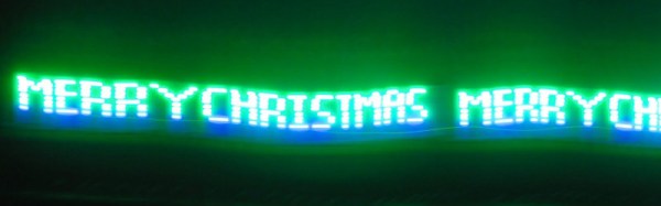
But [Andy Doswell] has recently taken an interesting alternate approach to this common technique. Rather than an array of LEDs that spin or rock back and forth in front of the viewer, his version of the display doesn’t move at all. Instead it has the viewer do the work, truly making it the “Chad” of POV displays. As the viewer moves in front of the array, either on foot or in a vehicle, they’ll receive the appropriate Yuletide greeting.

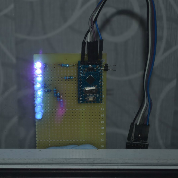
In a blog post, [Andy] gives some high level details on the build. Made up of an Arduino, eight LEDs, and the appropriate current limiting resistors on a scrap piece of perfboard; the display is stuck on his window frame so anyone passing by the house can see it.

On the software side, the code is really an exercise in minimalism. The majority of the file is the static values for the LED states stored in an array, and the code simply loops through the array using PORTD to set the states of all eight digital pins at once. The simplicity of the code is another advantage of having the meatbag human viewer figure out the appropriate movement speed on their own.

This isn’t the only POV display we’ve seen with an interesting “hook” recently, proving there’s still room for innovation with the technology. A POV display that fits into a pen is certainly a solid piece of engineering, and there’s little debate the Dr Strange-style spellcaster is one of the coolest things anyone has ever seen. And don’t forget Dog-POV which estimates speed of travel by persisting different images.

[Thanks to Ian for the tip.]

Easily Deboss Notebooks With A 3D Printed Stamp

While it’s arguably a bit closer to the “Arts & Crafts” region of the making spectrum upon which we don’t usually tread on account our l33t sense of superiority, we’ve got to admit that the quick and easy notebook customization demonstrated by [Sean Hodgins] is very compelling. We don’t put ink to dead trees with nearly the frequency we used to, but when we do it might as well be Hemingway-style with a little black Hackaday emblazoned notebook.

As demonstrated in the video after the break, the process starts by designing the stamp in your CAD package of choice. For optimal results [Sean] suggests fairly large capital letters, but with practice you should be able to get into some more creative fonts. Potentially you could even use the logo of your favorite hacking blog, but who are we to dictate what you do?

Whatever you chose, it needs to be mirrored and placed on a relatively thick backing. He recommends a 2 mm thick “plate” with the letters raised on top. You’ll want to print it at a high infill percentage, but even still it shouldn’t take more than 30 minutes or so to run off. Remember there tends to be diminishing returns on infill past 50%, so taking it all the way to 100% is not going to do much but expend more time and plastic.

Once printed, [Sean] hot glues the stamp to a block of wood since putting pressure on the printed piece directly would likely crack it. Then it’s just a matter of getting your notebook, printed stamp, and blocks of wood lined up in to a suitably beefy bench vise. Getting everything aligned is one of those things that easier said than done, so expect to mess up the first couple until you get the hang of it.

When the alignment looks good, crank it down and let it sit for a few minutes. If you’re embossing the design into actual leather, wetting it a bit before putting the pressure on should help. The final effect is understated but undeniably very slick; and with the Holidays rapidly approaching this might be an excellent way to knock out some legitimately thoughtful gifts.

Ultimately the idea here is something of a lightweight version of the 3D printed press break dies used to bend aluminum or the punch and die set used for steel plates. At this point it seems there’s enough evidence to say that 3D printed objects are certainly strong enough (in compression, at least) to put some legitimate work in.

Continue reading “Easily Deboss Notebooks With A 3D Printed Stamp”

Negative Voltage Pushes AVR To New Heights

If we say that a hacker is somebody who looks at a “solved” problem and can still come up with multiple alternative solutions, then [Charles Ouweland] absolutely meets the grade. Not that we needed more evidence of his hacker cred given what we’ve seen from him before, but he recently wrote in to tell us about an interesting bit of problem solving which we think is a perfect example of the principle. He wanted to drive a salvaged seven segment LED display with an AVR microcontroller, but there was only one problem: the display needs 15V but the AVR is only capable of 5V. So what to do?

As it turns out, the first step to solving the problem was verifying there was actually a problem to begin with. [Charles] did some experimentation and found that the display didn’t actually need 15V to operate, and in fact would light up well enough at just 6.5V. This lowered the bar quite a bit, but it was still too high to power directly from the chip.

There were a few common ways to solve this problem, which no doubt the Hackaday reader is well aware of. But [Charles] wanted to take the path less traveled. More specifically, the path with the least amount of additional components he had to put on his PCB. He set out to find the absolute easiest way to make his 5V AVR light up a 6.5V LED, and ended up coming with a very clever solution that some may not even know is possible.

He reasoned that if he connected the source pins of two BS170 MOSFETs to a voltage of -1.5V, even when the AVR pin was 0V, they would be still be receiving 1.5V. This virtual “step ladder” meant that once the AVR’s pin goes high (5V), the relative voltage would actually be 6.5V and enough to drive his LEDs. Of course the only problem with that is that you need to have a source for -1.5V.

Getting a negative voltage would normally require adding more components to the design (which he set out to avoid in the first place), but then he came up with another clever idea. To pull the trick off, he actually feeds the AVR 6.5V, but raises the ground voltage by 1.5V with the addition of two 1N4007 diodes. This way the AVR gets a voltage within its capabilities and still can provide a relative 6.5V to the LEDs.

One might say [Charles] took the Kobayashi Maru approach, and simply redefined the rules of the game. But such is the power of the confounding negative voltage.

NTP Morse Code Clock Powered By ESP8266

We’ve featured a great many unique clocks here on Hackaday, which have utilized nearly every imaginable way of conveying the current time. But of all these marvelous timepieces, the Morse code clock has the distinct honor of simultaneously being the easiest to construct and (arguably) the most difficult to read. As such, it’s little surprise we don’t see them very often. Which makes this latest entry into the field all the more interesting.

[WhisleyTangoHotel] has taken the basic concept of the Morse clock, which at its most simplistic could be done with a microcontroller and single LED, and expanded it into a (relatively) practical device. With both audio and visual signaling, and support for pulling the time from NTP, this is easily the most polished Morse code clock we’ve ever seen. Using it still requires you to have a decent grasp on Samuel Morse’s now nearly 200 year old encoding scheme of course, but on the bright side, this clock is sure to help keep your CW skills sharp.

For those following along at home, [WhisleyTangoHotel] provides a hand-drawn diagram to show how everything connects together in his Morse timepiece, but there’s nothing on the hardware side that’s likely to surprise the Hackaday reader. A single momentary push button represents the device’s sole user input, with the output being handled by a LED “tower” and speaker on their own respective pins on the microcontroller. Here a Adafruit Feather HUZZAH is used, but any ESP8266 would work in its place.

Of course, the advantage of using an ESP8266 board over your garden variety MCU is the Wi-Fi connectivity. This allows the clock to connect to an NTP server and get the current time before relaying it to the user. Some might think this overkill, but it’s really a critical feature; the lack of a proper RTC on the ESP means the clock would drift badly if not regularly synchronized. Assuming you’ve got a reliable Internet connection, this saves you the added cost and complexity of adding an external RTC.

[WhisleyTangoHotel] wraps up his blog post by providing his ESP8266 Arduino source code, which offers an interesting example in working not only with NTP and time zones on the ESP, but how to handle parsing strings and representing their principle characters in Morse code.

Interestingly enough, in the past we’ve seen a single LED clock that didn’t use Morse code to blink out the time, which might be a viable option as an alternate firmware for this device if you’re not in the Samuel Morse fan club.

Continue reading “NTP Morse Code Clock Powered By ESP8266”

Wearable Speeder Bikes Are Ready For A Night Out

While Hackaday is about as far from a fashion blog as you can possibly get, we have to admit we’re absolutely loving the [bithead942] Winter 2018 Collection. His wife and daughter recently got to model his latest must have design: wearable Star Wars speeder bikes; and judging by the video after the break they were certainly some of the best dressed at the Thanksgiving parade.

[bithead942] started the build by taking careful measurements of a vintage speeder bike model kit his wife had, which allowed to accurately recreate the iconic look of the vehicles as they were seen in Return of the Jedi . But to do them justice, the final “bikes” would need to be around three meters (ten feet) long, which immediately posed a problem. What kind of material could support itself over that length while still being light enough to wear for extended periods of time?

The answer came, as it often does, from the local hardware store. He found that a combination of Schedule 80 and 40 PVC pipe was a perfect material: strong enough to support the desired dimensions without bending, light enough that the final bike wouldn’t be uncomfortable to wear, easy to bend with heat, and perhaps best of all, cheap and readily available. The PVC frame was then covered with chicken wire and thin flexible foam to give it a filled out look without weighing them down.

Even though he had a strict weight limit on the build, [bithead942] couldn’t help but add in some electronics to complete the effect. The LED festooned control panel allows the ladies to trigger different sound effects from the movie stored on a Adafruit Mini FX Sound Board, which is connected to a 20W Class D amplifier and a pair of 400 watt car stereo speakers. He says the resulting playback was loud enough to hear outside during the parade, and only added a few pounds to the overall build.

These may be the bikes you’re looking for, but they’re definitely not the first we’ve featured on Hackakday. Meanwhile you’d be wise not to underestimate the lowly PVC pipe when designing your next project. From a hacked together drill press for your Dremel to a planetarium for you and your closest dozen or so friends, there’s little you can’t build with this plentiful material.

Continue reading “Wearable Speeder Bikes Are Ready For A Night Out”

Weaponized Networked Printing Is Now A Thing

It’s a fairly safe bet that a Venn diagram of Hackaday readers and those who closely follow the careers of YouTube megastars doesn’t have a whole lot of overlap, so you’re perhaps blissfully unaware of the man who calls himself [PewDiePie]. As such, you might not know that a battle between himself and another YouTube channel which uploads Bollywood music videos has reached such a fever pitch that his fans have resorted to guerrilla hacking to try to sway public opinion towards their side. It’s perhaps not the dystopian future we imagined, but it just might be the one we deserve.

To briefly summarize the situation, a hacker known only by the handle [TheHackerGiraffe] decided to help out Dear Leader by launching an automated attack against 50,000 Internet connected printers. When the hack was successful, the printer would spit out a page of digital propaganda, complete with fist ASCII art, that urged the recipient to go on YouTube and pledge their support for [PewDiePie]. There’s some debate about how many of the printers [TheHackerGiraffe] targeted actually delivered their payload, but judging by reactions throughout social media, it was enough to get the message out.

While the stunt itself may have come as a surprise, the methodology wasn’t. In fact, the only surprising element to the security researchers who’ve weighed in on the situation is that this hasn’t happened more often. It certainly isn’t the first time somebody’s done it, but the fact that this time its been connected to such a high profile Internet celebrity is putting more eyes on the problem then there have been in the past. Now that the proverbial cat is out of the bag, there are even websites springing up which claim to be purveyors of “Printer Advertising”. Odds are good this won’t be the last time somebody’s printer starts running off more than TPS reports.

We here at Hackaday don’t have much interest in the battle for YouTube supremacy. We’re just pulling for Dave Jones’s EEVBlog channel to join [AvE] in breaking a million subscribers. But we’re very interested in the technology which made this attack possible, how likely it is we’re going to see more people exploit it, and what are we supposed to do now that even our own printers can be turned against us?

Continue reading “Weaponized Networked Printing Is Now A Thing”

Hacking Your Way To A Custom TV Boot Screen

More and more companies are offering ways for customers to personalize their products, realizing that the increase in production cost will be more than made up for by the additional sales you’ll net by offering a bespoke product. It’s great for us as consumers, but unfortunately we’ve still got a ways to go before this attitude permeates all corners of the industry.

[Keegan Ryan] recently purchased a TV and wanted to replace its stock boot screen logo with something of his own concoction, but sadly the set offered no official way to make this happen. So naturally he decided to crack the thing open and do it the hard way The resulting write-up is a fascinating step by step account of the trials and tribulations that ultimately got him his coveted custom boot screen, and just might be enough to get you to take a screw driver to your own flat panel at home.

The TV [Keegan] brought was from a brand called SCEPTRE, but as a security researcher for NCC Group he thought it would be a fun spin to change the boot splash to say SPECTRE in honor of the infamous x86 microarchitecture attack. Practically speaking it meant just changing around two letters, but [Keegan] would still need to figure out where the image is stored, how it’s stored, and write a modified version to the TV without letting the magic smoke escape. Luckily the TV wasn’t a “smart” model, so he figured there wouldn’t be much in the way of security to keep him from poking around.

He starts by taking the TV apart and studying the main PCB. After identifying the principle components, he deduces where the device’s firmware must be stored: an 8 MB SPI flash chip from Macronix. He connects a logic analyzer up to the chip, and sure enough sees that the first few kilobytes are being read on startup. Confident in his assessment, he uses his hot air rework station to lift the chip off the board so that he can dive into its contents.

With the help of the trusty Bus Pirate, [Keegan] is able to pull the chip’s contents and verify its integrity by reading a few human-readable strings from it. Using the binwalk tool he’s able to identify a JPEG image within the firmware file, and by feeding its offset to dd, pull it out so he can view it. As hoped, it’s the full screen SCEPTRE logo. A few minutes in GIMP, and he’s ready to merge the modified image with the firmware and write it back to the chip.

He boots the TV back up and finds…nothing changed. A check of the datasheet for the SPI flash chip shows there are some protection bits used to prevent modifying particular regions of the chip. So after some modifications to the Bus Pirate script and another write, he boots the TV and hopes for the best. Finally he sees the object of his affection pop up on the big screen, a subtle change that reminds him every time the TV starts about the power of reverse engineering.