It Keeps On Going And… Arduino Edition

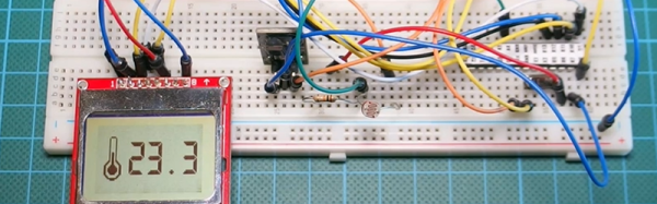
How long can you keep an Arduino circuit running on three AA batteries? With careful design, [educ8s] built a temperature sensor that lasts well over a year on a single charge of three 2250 mAH rechargeable cells (or, at least, should last that long).

Like most long-life designs, this temperature sensor spends most of its time sleeping. The design uses a DS18B20 temperature sensor and a Nokia 5110 LCD display. It also uses a photoresistor to shut off the LCD display in the dark for further power savings.

During sleep, the device only draws 260 microamps with the display on and 70 microamps with the display off. Every two minutes, the processor wakes up and reads the temperature, drawing about 12 milliamps for a very short time.

Along with the code, [educ8s] has a spreadsheet that computes the battery life based on the different measured parameters and the battery vendor’s claimed self discharge rate.

Of course, with a bigger battery pack, you could get even more service from a charge. If you need a refresher on battery selection, we covered that not long ago. Or you can check out a ridiculously complete battery comparison site if you want to improve your battery selection.

Continue reading “It Keeps On Going And… Arduino Edition”

Arduino (PCI) Express

It is almost impossible these days to find a PC with old ISA card slots. Full size PCI card slots are in danger of going the same way. Many PCs today feature PCI Express connectors. PCI Express offers a lot of advantages including a small size, lower pin count, and a point-to-point serial bus topology that allows multiple simultaneous transfers between different pairs of end points. You’ll find PC Express connectors in things other than PCs too, including a lot of larger embedded systems.

If you ever wanted to prototype something on PCI Express, you’d usually turn to an FPGA. However, [moonpunchorg] posted a workable design for an Arduino on a mini PCI Express board. (As [imroy264] points out in the comments, the board is using the USB port present on the PCI-E connector.) The design files use KiCAD so it should be fairly easy to replicate or change. Naturally, there are pins on the edges to access I/O ports and power. You do need to use ISP to program the Arduino bootloader on the chip.

The board appears to a host computer as a SparkFun as a Pro Micro 3.3V board, and from there you could easily add function to a computer with a PCI Express slot using nothing more than the Arduino IDE. The board is known to work with the VIA VAB-600 Springboard and VIA VAB-820 boards, although it is likely to work with other PCI Express hosts, too.

Another IoT Platform In The (Blue)Mix

Many major companies (Intel, Oracle, Atmel, and IBM, for example) are competing to be the standard interconnect fabric for the Internet of Things. As a developer, it is hard to cut through the marketing hype and decide which platform is the best for you and your application. Luckily, there’s a plethora of projects on the web that showcase these frameworks. These project sites are an easy way to evaluate the strengths and weaknesses of IoT frameworks in practical applications without having to develop prototypes yourself.

[diyhacking], for example, posted a demo of using IBM’s Bluemix along with a Raspberry Pi, to do some simple home automation tasks. The project hardware is modest, using a PIR motion sensor and a relay to control an AC load. However, that’s good because it lets you focus on the Bluemix tools. The example client and server software is less than 200 lines of Python.

Bluemix looks like it has good integration with the Raspberry Pi and features a simulator so you can work without real hardware for development. Bluemix does offer a free plan (with limits), but the fee options may be a turn off to some IoT hackers.

Continue reading “Another IoT Platform In The (Blue)Mix”

Better 3D Prints By Mixing Slicing Techniques

Most 3D printing projects start with a 3D model of some kind. Slicing programs transform the model into gcode. The gcode file contains the commands that actually drive your printer. There are different ways to slice a model and sometimes you want to use more than one on a single model. I’ve been working on a way to make that easier.

When you slice a 3D printing model, you can select different attributes for the resulting gcode file. For example, you might set the slicer to produce different infill density, temperatures, or print speeds. These settings can have a big impact on your printing results. For example, a piece that needs high strength might require a denser infill  than some trinket or key chain. You might want an artistic piece to have a finer layer height than some internal part for some gadget no one will ever see.

One Size Fits All?

The problem is that for most open source slicers, these settings will apply to the entire model. Cura has some plugins that can change settings at different Z heights, and Slic3r can vary layer height, but in the general case, what you set for the slicer will apply to the entire model. Of course, a gcode file is nothing more than a text file, so if you are industrious, you can manually merge two or more files into one.

A manual merge is a pain, which is why I wrote gblend. It can stitch together gcode files to get various effects. The program takes multiple gcode files in as inputs and can combine them in different ways. The most useful feature allows you to get a certain number of layers from each source file and combine them into a single print. Measurements are in millimeters, so you don’t have to worry about layer numbers. The entire process is much easier than anything else I’ve come across.

Continue reading “Better 3D Prints By Mixing Slicing Techniques”

Learn FPGAs In Your Browser

FPGAs aren’t really programmed, they are configured. Most designers use Verilog or VHDL to describe the desired circuit configuration. Developers typically simulate these configurations before committing them to silicon (a good habit, especially if you ever graduate from FPGAs to ASICs where changes are very expensive). That simulation takes a lot of software you have to install and learn, right?

Not necessarily. You can do e-mail, word processing, and PCB layout in your browser. Why not FPGA design? The EDAPlayground website provides two editor views: one for your main “code” and another for the testbench (the simulation driver you use to test your design). You can even open multiple files, if you have a complex design.

Once you’ve entered your Verilog or VHDL (or picked one of many examples) you can run the simulation and see the result right in your browser. No software to install, and–outside of actually learning VHDL or Verilog–not much learning curve.

As [Strauburn], [combinatorylogic], and others commented on our recent post about a VHDL CPU, you can do a lot of learning without ever having your hands on real hardware. The web site gives you access to several different tools (useful if you want to see how your code will behave on different tools) and also many standard verification libraries. There are limited synthesis tools, but honestly, if you want to go to real hardware, you are going to want the vendor tools for the specific FPGA you are using.

Continue reading “Learn FPGAs In Your Browser”

A Breadboard In A Browser

[Flownez] sent in a tip that a port of the venerable Falstad circuit simulator is now available that doesn’t require Java (it uses HTML 5). This is a welcome port since some modern browsers (particularly Chrome) make it difficult to run Java applets and prevented the Falstad simulator’s execution.

spice2
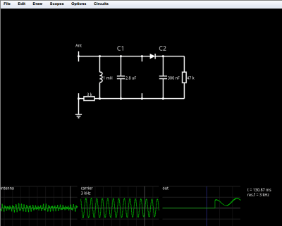
Like the original simulator, this one is great to show a classroom circuits and encourage building or studying circuits in the browser. There’s no extra software to install, which is handy for an impromptu demo. Another cool feature is the visualization of current flow as animated dots. The dots move in the direction of the current flow and the speed of motion is proportional to the amount of current. Watching a capacitor charge with the moving dots is very illustrative. You can also view data in a scope format or hover the mouse over things to read their values.

You can open a blank circuit and add quite a few components (use the right click button on your mouse or the menu to add components and wires). However, you can also pick from a number of predefined circuits ranging from the simple (a voltage divider, for example) to the illustrative (a PLL frequency doubler comes to mind). There’s even an AM radio (see below) that you can tune to find several “stations” by varying the tuning capacitor’s value. Circuit elements include many types of analog and digital components.

Continue reading “A Breadboard In A Browser”

Police LiDAR Tear Down

Most police departments made a big switch from RADAR to LiDAR after consumers starting buying RADAR detectors. A lot of those LiDAR units are now out there on the surplus market. If you don’t have $500 or so to buy a LiDAR gun just to see what makes it tick, you are in luck. [Alexei Polkhanov] spent an hour tearing down a  UltraLyte LTI 20-20 LR 100 so you don’t have to.

An hour seems like a lot for a tear down video, but [Alexei] speeds up through the boring parts, and spends a lot of time talking about the optics and how the device works (with a lot of hand drawn diagrams). He also puts it back together and connects  a scope to show the electronic operation of the device.

He mentions the display and control board uses a serial interface to talk to the controller board. There is also an unpopulated header on the main board that is clearly a serial port, probably for reprogramming the onboard microcontroller. With a little reverse engineering work, this LiDAR gun ought to be highly hackable.

In addition to the display and control board, the unit contains a high voltage supply for the laser and the photodiode. Making a power supply to drive the laser that is clean enough not to disturb the sensor is one of the design drivers and it shows. The power supply is a large and complex board by comparison to the other boards in the system.

Continue reading “Police LiDAR Tear Down”