Some FDM filaments are pretty brittle even if properly dried and stored, especially those which contain carbon fiber (CF) or similar additives like glass fiber (GF). This poses a problem in that these filaments can snap even within the PTFE tube as they’re being guided towards the extruder. Here a community theory is that having an actively heated chamber can help prevent this scenario, but is it actually true? [Dr. Igor Gaspar] of the My Tech Fun YouTube channel gave this myth a try to either confirm or bust it.
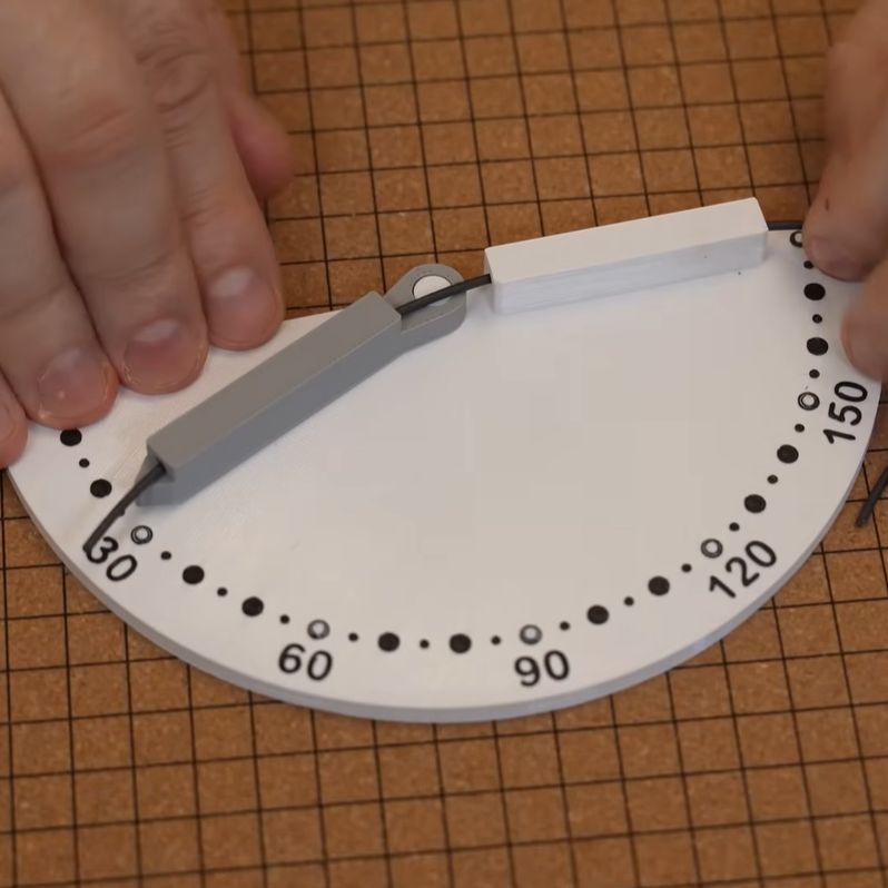
The comments suggested that heating the chamber to 65°C will help, but there’s little information online to support this theorem. To test the claim, a heated chamber was used along with a bending rig to see at which angle the filament would snap. In total five different filaments from three manufacturers (Polymaker, Qidi and YXPolyer) were tested, including Qidi’s PET-GF and PAHT-GF as the sole non-CF filaments.
A big question is how long exactly the filament will spend inside the heated chamber after making its way from the spool, which would be about 2.5 minutes with a 500 mm tube. For the test 5 minutes was used for the best possible result. Despite this, the results show that even with the standard deviation kept in mind, the heating actually seems to make the filaments even more brittle.
Considering that in general CF seems to simply weaken the polymer matrix after printing, this finding adds to the question of whether these CF and GF-infused filaments make any sense at all.
Continue reading “Testing Whether Heated Chambers Help Brittle Filaments”