A group of researchers have built an algorithm for finding hidden connections in artwork.
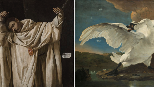
The team, comprised of computer scientists from MIT’s Computer Science and Artificial Intelligence Laboratory (CSAIL) and Microsoft, used paintings from the Metropolitan Museum of Art and Amsterdam’s Rijksmuseum to demonstrate these hidden connections, which link artwork that shares similar styles, such as Francisco de Zurbarán’s The Martyrdom of Saint Serapion (above left) and Jan Asselijn’s The Threatened Swan (above right). They were initially inspired by the “Rembrandt and Velazquez” exhibition in the Rijksmuseum, which demonstrated similarities between the artists’ work despite the former hailing from the Protestant Netherlands and the latter from Catholic Spain.
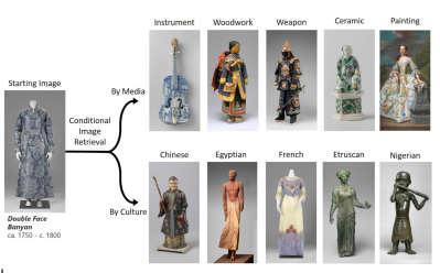
The algorithm, dubbed “MosAIc”, differs from probabilistic generative adversarial network (GAN)-based projects that generate artwork since it focuses on image retrieval instead. Rather than focusing solely on obvious factors such as color and style, the algorithm also tries to uncover meaning and theme. It does this by constructing a data structure called a conditional k-nearest neighbor (KNN) tree, which provides a tree-like structure where branches off a central image indicate similarity to the image. In order to query the data structure, these branches are followed until the closest match to an image in a dataset is found. In further iterations, it prunes unpromising branches in order to improve its time for new queries.
Some results from running the algorithm against museum collections were finding similarities between the Dutch Double Face Banyan and a Chinese ceramic figurine, traced to the flow of porcelain and iconography from the Chinese to the Dutch in the 16th to 20th centuries.
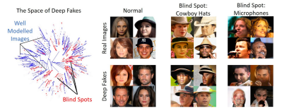
A surprising result of this study was discovering that the approach could also be applied to find problems with deep nerual networks, which are used for creating deepfakes. While GANs can often have blind spots in their models, struggling to recreate certain classes of photos, MosAIc was able to overcome these shortcomings and accurately reproduce realistic images.
While the team admits that their implementation isn’t the most optimized version of KNN, their main objective was to present a broad conditioning scheme that is simple but effective for applications. Their hope is to inspire related researchers to consider multi-disciplinary applications for algorithms.