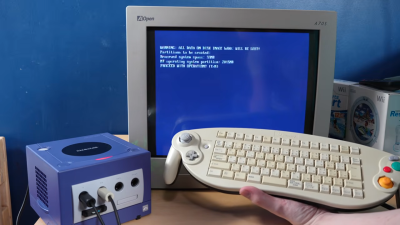
The Nintendo GameCube is known for playing the best version of Smash Bros. and its vaguely rectangular aesthetic. It’s not particularly known for running a workstation OS from the mid-1990s. However, with a little work, your diminutive purple console could also boot up Windows NT if you really wanted it to.
You’ll want a controller that looks *like* this, but not this exact model—because [Jiga Tech] couldn’t get this keyboard controller to work with the ported version of Windows NT.This is fundamentally possible because, once upon a time, Microsoft built a PowerPC version of Windows NT. The work to make it compatible with the GameCube was performed by a group of contributors—[Rairii], [NTx86], and [stonedDiscord]—with the resulting port made available on Github. It won’t just run on the GameCube, either. You can also boot it on the Wii, and within the Wii-U’s vWii mode, as well.
If you’re interested in seeing what this looks like, there’s a great video from [Jiga Tech] on YouTube that outlines the install process. Just note that the GameCube never really came with a proper keyboard. If you want textual input, you’ll have to fuss with a range of controller-entry methods, or get one of the rare GameCube controllers that had an entire keyboard in the middle. We’re not even kidding, they did exist.
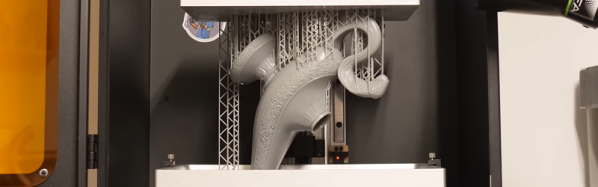
Generally the idea with photopolymers as used with resin 3D printing is that the process only works in a single direction as with all thermosets: after polymerization under influence of UV light they become an inert lump of plastic. Being able to turn these lumps back into resin would of course be ideal, as it would make recycling incredibly easy. Here depolymerizable resin turns out to be a thing, with 3Dresyn being one company that sells additives and resin which enable this (found via Fabbaloo).
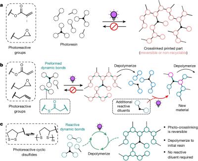
Irreversible (thermoset), partial and full depolymerization. (Credit: Machado et al., Nature, 2024)
These additives and resins come in essentially two flavors based on which temperature they depolymerize at, which can be at either 80°C or 150°C. This comes at a cost, of course, with the ready-to-use resin coming in at an eyewatering €833.00 for a 1 kg bottle, a factor only slightly helped by the reusability aspect.
From a more technical perspective this depolymerization feature is fascinating, as it addresses the one aspect of thermosets (like SLA and epoxy resins) that thermoplastics have as advantage, especially from a recycling view. This type of circular photopolymer appears to be quite novel, with an article by [Machado] et al. from 2024 claiming to have demonstrated the first resin that can be photopolymerized, depolymerized and subsequently again photopolymerized in a closed loop.
In the demonstration by [Machado] et al. the depolymerization is achieved using dynamic disulfide bonds, with the pulverized printed samples put into a 2-methyl-tetrahydrofuran (MeTHF) solvent. After heating at 80°C for 3 hours with an inert atmosphere, most of the photopolymerized material had returned to its original, pre-printing state. In a more recent 2025 study by [Bo Yang] et al. an approach using catalytic thermal dissociation of dithioacetal bonds was explored.
Based on the available information by 3Dresyns it would seem that their product is closer to this latter approach, with depolymerization requiring putting the part into an oven at the target temperature for up to an hour, presumably in some kind of suitable container. This is said to target elements like sacrificial molds, reusable tooling and jigs that would otherwise be discarded, or need to melt like a thermoplastic instead of acting like a thermoset. Whether a solvent like MeTHF is required as in the two cited studies is sadly unclear based on a quick scan of the site.
The idea to pursue this came from off-the-shelf panel displays commonly used for power supply builds and other such equipment. These come in relatively standard sizes and are designed from the outset to slot neatly into a panel with a bezel that covers any ugly edges or awkward gaps.
The build began with a 48 x 29 mm enclosure grabbed from an off-the-shelf power panel meter. There are two PCBs—one holding the regulator and other equipment to run the display, the other carrying a set of screw terminals that make it easy to wire up the display to a piece of equipment. The SSD1306-compatible OLED screen itself connects to the first board with a flat flex cable, as is the norm.
If you find yourself often wanting to pop a small display into a piece of custom test equipment, this might be relevant to your interests. Files are on GitHub for the curious.
A reverse-engineering effort targeted at the EBC-A20 served as the basis for the work. The battery tester is ultimately controlled by a simple serial interface, running at 9600 bps, 8 bits, with odd parity. Armed with a relatively complete understanding of the commands used to control the device, [Kazhuu] was able to whip up a simple web app to control the device instead, using WebUSB to access the device over a USB-to-serial converter, though a desktop version for Linux and Windows is also available. If you’ve got one of these battery testers sitting on your bench, using the app is as simple as pointing your browser here with the device plugged in via USB. Then you can run basic load tests on battery cells and graph the results right on your computer without having to deal with the proprietary software.
Of course, if you don’t like the EBC-A20 battery tester, you could always build your own. If you’re whipping up your own test hardware on the lab bench, don’t hesitate to notify us on the tipsline.
Running the show is a Wemos D1 devboard equipped with the ESP8266 microcontroller. It’s hooked up to a pair of OLED displays over I2C. The displays are placed in a 3D printed assembly that aims each one at a beam-splitter cube. This bounces light projected into one face through 90 degrees, and out another face. By leveraging this, it’s possible to aim each display at one face and bounce it out another, such that looking at either side of the beamsplitter cube shows a different image. Since the beamsplitter cube also allows some light to be transmitted directly through as well, the image from each display appears to float in space.
[Julius] notes that this setup is being used in a puzzle box game, while wondering whether there’s any other fun ways to leverage this technique. We’ve seen some other neat holographic displays before, too, like this neat Holochess build.
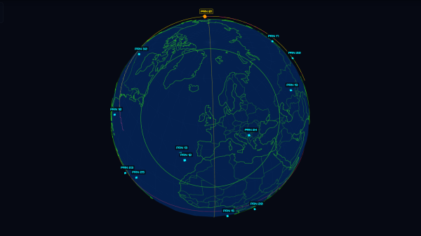
Billions of people use GPS on a daily basis, along with the various other satellite navigation systems available today. But few of us spend much time contemplating the fleet of satellites above us that actually makes the system work. [Robert Wolf] has, though, and he’s built a simple visualizer that displays just what those space birds are doing at any given time.
The visualizer runs right in the browser, and displays a cluster of GPS satellites in a 3D view around the Earth. The tool also offers a list of satellites and related data, including signal-to-noise ratio of the received signals from each one, and the ability to play back satellite positions from previous days. The satellite positions are captured from a GPS receiver that [Robert] operates in the UK.
The view isn’t global or complete, since the receiver can only see a certain number of satellites from its location, but it nevertheless gives an idea of where a subset of GPS satellites are flying above the globe. Depending on the selected view, it’s possible to see the satellites superimposed over the world map itself — or from a distant observer’s perspective, as if looking at the Earth from a distance, among other options.
If you’ve ever wanted an intuitive idea about where the GPS satellites live, this tool is a great way to understand it. We’ve also previously discussed the wide range of GPS alternatives that have been developed over the years. If you’ve got your own GPS hacks brewing in the home lab, don’t hesitate to let us know on the tipsline.
There was a particularly tense moment aboard the International Space Station earlier this month, with NASA directing their astronauts to secure themselves in the Dragon capsule and prepare for a potential return to Earth while their Russian counterparts engaged in what we now know to have been some impromptu demolition work on their side of the orbiting complex.
Despite objections from their American partners, Roscosmos had given their cosmonauts the go-ahead to drill and cut into the walls of the Zvezda module — one of the core components of the ISS which has been in orbit since 2000 — to try and identify and ultimately repair persistent leaks that have been venting the Station’s atmosphere out into space for several years. We may never know the exact nature of the behind-the-scenes communication that went on between the two space agencies, but in the end the Russians abandoned their plan and NASA’s personnel were told to resume their normal duties.
But where do things go from here? Although it’s true the International Space Station is entering its final years, the mission isn’t over yet, and that means the two countries need to continue to work together if they hope to get any science done in the time they have left.
At this point there hasn’t been any official word from either agency, but sources that wish to remain anonymous have been dropping hints, and that’s got the rumors swirling. With the understanding that anything is still possible, at this point it looks like Russia is going to abandon any further attempts to repair the leak and instead seal off the crippled compartment of the Zvezda module. This won’t solve all the problems, and in fact will create some new ones. But if that’s what it will take to keep the peace with NASA until Station operations wind down, it’s apparently a bargain they’re willing to make.