Share Your Projects: Making Helpful PCBs

When it comes to things that hackers build, PCBs are a sizeable portion of our creative output. It’s no wonder – PCB design is a powerful way to participate in the hardware world, making your ideas all that more tangible with help of a friendly PCB fab. It’s often even more lovely when the PCB has been designed for you, and all you have to do is press “send” – bonus points if you can make a few changes for your own liking!

A lot of the time, our projects are untrodden ground, however, and a new design needs to be born. We pick out connectors, work through mechanical dimensions, figure out a schematic and check it with others, get the layout done, and look at it a few more times before sending it out for production. For a basic PCB, that is enough – but of course, it’s no fun to stop at ‘basic’, when there’s so many things you can do at hardly any cost.

Let’s step back a bit – you’ve just designed a board, and it’s great! It has all the chips and the connectors you could need, and theoretically, it’s even supposed to work first try. Now, let’s be fair, there’s an undeniable tendency – the more PCBs you design, the better each next one turns out, and you learn to spend less time on each board too. As someone with over two hundred PCBs under her belt, I’d like to show you a bunch of shortcuts that make your PCB more helpful, to yourself and others.

There’s a few ways that you can share your PCB projects in a more powerful way – I’d like to point out a few low-hanging fruits, whether README.md files or markings on the PCB itself. I’ve been experimenting quite a bit with external and embedded documentation of PCBs, as well as PCB sharing methods, got some fun results, and I’d like to share my toolkit through a few punchy examples and simple tricks. I’d also like to hear about yours – let’s chat! Continue reading “Share Your Projects: Making Helpful PCBs”

Minimal USB Device Connects With Just A Couple Of Resistors

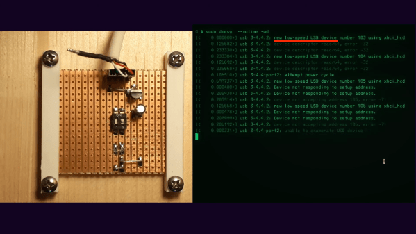
If you’re like most of us, your basic approach to building something boils down to: “What’s the minimum amount I need to do to get this to work?” It’s not a bad strategy in general, but the minimal build is rarely enough to meet all the requirements, as this extremely minimal but functional USB device illustrates.

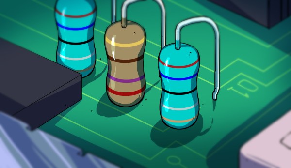
Functional, yes, but as [TM] explains, only if you define functional as being recognized by your operating system. The BOM for that job turns out to be really small — a 3.3-volt regulator, its capacitor, and a pair of resistors connected to a DIP switch. The resistors, 1.5k each, are connected to the D+ and D- lines of the USB connector and pull their respective lines up to 3V3 when their switch is closed. If the D- switch is thrown, it indicates a low-speed connection is requested, while D+ requests a speedier connection. Either way, its enough to get the familiar “USB connect” sound in Windows, and to see it listed in Device Manager or dmesg on Linux.

With no microcontroller to return a device descriptor, not much else happens, of course, but it’s still interesting that so little is needed to at least get the host machine to know that something was plugged in. And that alone has some diagnostic value; as [TM] points out, you could use this circuit to test that the physical port on the host at least minimally works.

He runs through a few other potentially useful scenarios, but really, the best use of something like this is to educate yourself on the lowest levels of USB connection negotiation. If you want to dive deeper into USB-C specifically, we suggest you check out [Arya Voronova]’s “All About USB-C” series.

Continue reading “Minimal USB Device Connects With Just A Couple Of Resistors”

Giving A Tinge Of Color To The Mars Map Courtesy Of The UAE’s Hope Orbiter

Since the United Arab Emirates’ Hope (“Al-Amal”) orbiter made it safely into orbit around Mars on February 9, 2021, it’s been busy using its onboard instruments to measure everything it could about not only the planet’s atmosphere but also its surface and how both change seasonally. The first months of results of these detailed captures of Mars have now been released in the form of the full-color Mars Atlas website, and a pretty well made PDF version of the Atlas that can be downloaded from the website.

Although the Emirates Mars Mission is not the first to capture the surface or seasons of Mars — with the Mars Reconnaissance Orbiter (MRO)’s Context Camera  (CTX) having gifted us the result of many thousands of captures in a massive monochrome mosaic of Mars’ surface — it’s good to remember that Hope is only just getting started. The current atlas is the result of about 3,000 captures from the Emirates eXploration Imager (EXI) multi-band camera (with better than 8 km spatial resolution), with new images in the pipeline.

Hope has transitioned from a low 1,072 km orbit to a higher, science orbit on March 29, which gives the orbiter a good view of the seasonal transitions on the Red Planet. Along with data from other current Mars orbiters, we should be able to piece together the most detailed atlas yet, even before more helicopters will zip along Mars’ surface.

Arctos Robotics: Build A Robot Arm Out Of 3D Printer Spares?

ARCTOS is a 6-DOF robot arm based upon 3D printed mechanics running a modified version of GRBL firmware. Let’s get this straight now, the firmware is open source, but the hardware plans are a paid download, but for less than forty euros, we reckon the investment would be well worth it, judging from the quality of the build instructions and the software support already in place. Continue reading “Arctos Robotics: Build A Robot Arm Out Of 3D Printer Spares?”

A 3D printed copper aerospike engine cutaway showing the intricate, organic-looking channels inside. It is vaguely reminiscent of a human torso and lungs.

3D Printed Aerospike Was Designed By AI

We’re still in the early days of generatively-designed objects, but when combined with the capabilities of 3D printing, we’re already seeing some interesting results. One example is this new copper aerospike engine. [via Fabbaloo]

A collaboration between startups Hyperganic (generative AI CAD) and AMCM (additive manufacturing), this 800 mm long aerospike engine may be the most complicated 3D print yet. It continues the exciting work being done with 3D printing for aerospace applications. The complicated geometries of rocket nozzles of any type let additive manufacturing really shine, so the combination of generative algorithms and 3D printed nozzles could result in some big leaps in coming years.

Aerospikes are interesting as their geometry isn’t pressure dependent like more typical bell-shaped rocket nozzles meaning you only need one engine for your entire flight profile instead of the traditional switching mid-flight. A linear aerospike engine was one of the main selling points for the cancelled VentureStar Space Shuttle replacement.

This isn’t the only generative design headed to space, and we’ve covered a few projects if you’re interested in building your own 3D printed rocket nozzles or aerospike engines. Just make sure you get clearance from your local aviation regulator before your project goes to space!

A Tale Of Two Pulse Modulators

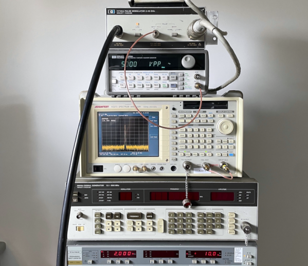
In the realm of test equipment, there are a number of items that you don’t know you need until you need one. That’s probably the case with the HP11720A pulse modulator. [Tom] acquired two of these even though, by his own admission, he had “no need for these things.” We’d like to say we don’t get that, but — alas — we do.

The good news, though, is he used one of them to measure the quality of some coax cable and shared the exercise with us in the post and a video, which you can watch below. The device can generate pulses with extremely fast rise and fall times (under 10 nanoseconds) at frequencies from 2 to 18 GHz. These were often used in pulsed radar applications and probably cost quite a bit more new than [Tom] shelled out for them.

Continue reading “A Tale Of Two Pulse Modulators”

Converting A B&W Enlarger For Colour Analog Photo Printing

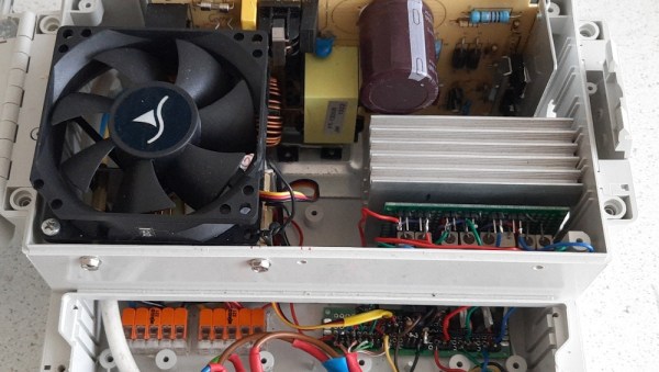
[Koraks tinkers] was gifted a gargantuan photographic enlarger, a Durst Laborator 138 s, which is a unit designed specifically for black and white usage only. This was not good enough for [Koraks] so down the rabbit hole of conversion to colour we go! The moral of the story is this: if you can’t find it, build it. The hacker mentality. After wasting time and effort trying to source a period colour head for the thing, [Koraks] did the decent thing and converted what was already in front of them.

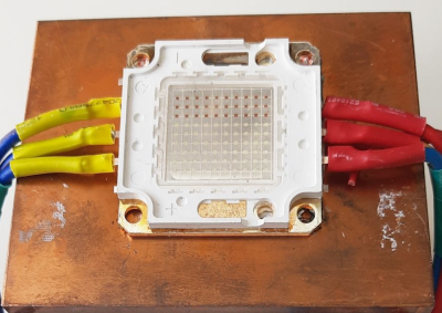
A hacked Chinese-sourced COB array. This is no use.

Now, if you’re thinking this process is simply a matter of ripping out the tungsten bulb and sticking a high-power RGB array in there, then you’re going to be disappointed! You see, colour photography of the era — specifically the RA4 process in this case — requires careful colour calibration and is heavily biased towards the red end of the visible spectrum, due to the colour curve of those tungsten bulbs we touched upon earlier.

Attempt 2: With a heavy bias towards the red end of the spectrum

The first attempt at using an off-the-shelf COB array was a bust — it simply wasn’t bright enough once the light had passed through the diffuser plate, and the light path losses were too high to expose the RA4 paper sufficiently, especially at the red end of the spectrum. Quite simply this is due to the reduced energy of red photons (compared to blue) making the desired chemical reaction rate too low. The solution is more power.

Another issue that quickly raised itself was that 8-bits of PWM control of the RGB components was inadequate since the ratio of blue to red required was so skewed, that only a few effective bits of blue channel control were usable, and that was far too granular to get the necessary accuracy.

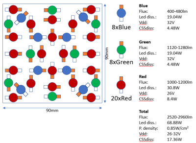
[Koraks’] approach was to custom build an LED array with twenty red 3W LEDs and eight each of the green and blue devices. 12-bits of PWM resolution was delivered via a PCA9685 PWM controller, that also handily controlled the cooling fans. The whole thing was hooked up to an Arduino Nano, with an MCP23016 expander board performing the duty of interfacing the rotary encoders and trigger footswitch. In fact, several iterations of the LED array have been constructed and this four-part blog series (Part1, Part2, Part3, Part4) lays out the whole story in all its gory detail for your entertainment. Enjoy!

COB LED arrays are pretty nifty, checkout turning them into 7-segment displays, just because. If all you want is raw power, we reckon that 100W “should be enough for anyone…”

Thanks [macsimski] for the tip!

Update: Corrected the article header from ‘exposer head’ to ‘enlarger’ for clarity at the request of the project author.