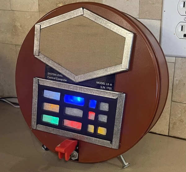
USB Drive Keeps Your Secrets… As Long As Your Fingers Are Wet?

[Walker] has a very interesting new project: a completely different take on a self-destructing USB drive. Instead of relying on encryption or other “visible” security features, this device looks and works like an utterly normal USB drive. The only difference is this: if an unauthorized person plugs it in, there’s no data. What separates authorized access from unauthorized? Wet fingers.

It sounds weird, but let’s walk through the thinking behind the concept. First, encryption is of course the technologically sound and correct solution to data security. But in some environments, the mere presence of encryption technology can be considered incriminating. In such environments, it is better for the drive to appear completely normal.

Toggling the chip enable (CE) pin will hide the drive’s contents.

The second part is the access control; the “wet fingers” part. [Walker] plans to have hidden electrodes surreptitiously measure the resistance of a user’s finger when it’s being plugged in. He says a dry finger should be around 1.5 MΩ, but wet fingers are more like 500 kΩ.

But why detect a wet finger as part of access control? Well, what’s something no normal person would do right before plugging in a USB drive? Lick their finger. And what’s something a microcontroller should be able to detect easily without a lot of extra parts? A freshly-licked finger.

Of course, detecting wet skin is only half the equation. You still need to implement a USB Mass Storage device, and that’s where things get particularly interesting. Even if you aren’t into the covert aspect of this device, the research [Walker] has done into USB storage controllers and flash chips, combined with the KiCad footprints he’s already put together means this open source project will be a great example for anyone looking to roll their own USB flash drives.

Regular readers may recall that [Walker] was previously working on a very impressive Linux “wall wart” intended for penetration testers, but the chip shortage has put that ambitious project on hold for the time being. As this build looks to utilize less exotic components, hopefully it can avoid a similar fate.

Re-reclaimed From Nature: Resurrecting A DT80 Terminal

When Datamedia announced their new DT80 terminal as a VT100 killer back in 1979, they were so confident of its reliability, they threw in a full one-year warranty. Now, decades later, that confidence is once more put to the touch after [RingingResonance] fished one such terminal out of a creek by an old illegal dumping site. Not knowing what to expect from the muck-ridden artifact, his journey of slowly breathing life back into the device began.

Brings new meaning to the term “rooted”

Considering the layers of mud and roots already growing all over the main board, one can only assume how long the terminal has actually been in there. But cleaning it from all that was only the beginning: some components were missing, others turned out to be broken, including some of the ROMs, which [RingingResonance] speculates may have been caused by lightning which determined the DT80’s fate in the first place.

That’s when the adventure really started though, digging deep into the terminal’s inner life, eventually writing a debugger and own firmware for it. That code, along with all other research, notes, and links to plenty more pictures can be found in the GitHub repository, and is definitely worth checking out if you’re into the technologies of yesteryear.

Despite the DT80’s claimed superiority, the VT100 prevailed and is the terminal that history remembers — and emulates, whether as tiny wearable or a full look-alike. But this fall into oblivion was also part of [RingingResonance]’s motivation to keep going forward restoring the DT80. Someone had to. So if you happen to have anything to contribute to his endeavours or share with him, we’re sure he will appreciate you reaching out to him.

Continue reading “Re-reclaimed From Nature: Resurrecting A DT80 Terminal”

Hackaday Prize 2022: Soviet Geiger Counter Gets WiFi

[Marek] has an impressive collection of old Soviet-style Geiger counters. These are handy tools to have in some specific situations, but for most of us they would be curiosities. Even so, they need some help from the modern world to work well, and [Marek] has come up with some pretty creative ways of bringing them into the 21st century. This version, for example, adds WiFi capabilities.

This build is based on the STS-5 Geiger tube but the real heavy lifting is handled by an ESP8266 which also provides a wireless network connection. There are some limitations to using an ESP8266 to control a time-sensitive device like a Geiger tube, especially the lack of local storage, but [Marek] solves this problem by including a real-time clock and locally caching data until a network connection is re-established. Future plans for the device include adding temperature and atmospheric temperature sensors.

Eventually this Geiger counter will be installed in a watertight enclosure outside so [Marek] can keep an eye on the background radiation of his neighborhood. Previously he was doing this with another build, but that one only had access to the network over an Ethernet cable, so this one is quite an upgrade.

Demonstrate Danger, Safely

Dan Maloney and I were talking about the chess robot arm that broke a child’s finger during the podcast, and it turns out that we both have extreme respect for robot arms in particular. Dan had a story of a broken encoder wheel that lead to out-of-control behavior that almost hit him, and I won’t even get within striking distance of the things unless I know they’re powered off after seeing what programming errors in a perfectly functioning machine can do to two-by-fours.

This made me think of all the dangerous things I’ve done, but moreover about all the intensely simple precautions you can to render them non-risky, and I think that’s extremely important to talk about. Tops of my list are the aforementioned industrial robot arm and high powered lasers.

Staying safe with an industrial robot arm is as easy as staying out of reach when it’s powered. Our procedure was to draw a line on the floor that traced the arm’s maximum radius, and you stay always outside that line when the light is on. It’s not foolproof, because you could hand the ’bot a golf club or something, but it’s a good minimum precaution. And when you need to get within the line, which you do, you power the thing down. There’s a good reason that many industrial robots live in cages with interlocks on the doors.

Laser safety is similar. You need to know where the beam is going, make sure it’s adequately terminated, and never take one in the eye. This can be as simple as putting the device in a box: laser stays in box, nobody goes blind. If you need to see inside, a webcam is marvelous. But sometimes you need to focus or align the laser, and then you put on the laser safety glasses and think really hard about where the beam is going. And then you close the box again when you’re done.

None of these safety measures are particularly challenging to implement, or conceptually hard: draw a line on the floor, put it in a box. There were a recent series of videos on making Lichtenberg figures safely, and as a general rule with high voltage projects, a great precaution is a two-button deadman’s switch box. This at least ensures that both of your hands are nowhere near the high voltage when it goes on, at the cost of two switches.

If all of the safety precautions are simple once you’ve heard them, they were nothing I would have come up with myself. I learned them all from other hackers. Same goes with the table saw in my workshop, or driving a car even. But since the more hackery endeavors are less common, the “common-sense” safety precautions in oddball fields are simply less commonly known. It’s our jobs as the folks who do know the secrets of safety to share them with others. When you do something dangerous, show off your safety hacks!

Fix Old Caps, But Keep That “Can Capacitor” Look

Vintage electronics and capacitor replacements tend to go hand-in-hand. Why? Because electrolytic capacitors just don’t last, not the way most other components do, anyway.

The metal terminal ring and the central plate are kept for re-use, and the metal case re-crimped after the internals of the capacitor are replaced with a modern equivalent.

It’s one thing to swap old caps with modern replacements, but what about electronics where the components are not hidden away, and are an important part of the equipment’s look? [lens42] shares a method for replacing antique can-style capacitors in a way that leaves them looking completely original. All it takes is some careful application of technique.

The first thing to do is carefully file away the crimp of the metal can until one can release the ring and plate that hold the terminals. Once that is off, the internals can be pulled from the metal can for disposal. Since the insides of the old cap won’t be re-used, [lens42] recommends simply drilling a hole, screwing in a lag bolt to use as a handle, and pulling everything out. There’s now plenty of space inside the old can to hold modern replacements for the capacitor, and one can even re-use the original terminals.

That leaves the job of re-crimping the old can around the terminal ring to restore a factory-made appearance. To best do this, [lens42] created a tapered collar. Gently hammering the can forces the bottom into the taper, and the opening gradually crimps around the terminal ring. It’s also possible to carefully hammer the flange directly, but the finish won’t be as nice. This new crimp job may not look exactly the same as before, but once the cap is re-installed into the original equipment, it won’t be possible to tell it has been modified in any way.

If this sounds a bit intimidating, don’t worry. [lens42] provides plenty of pictures. And if this kind of thing is up your alley, you may want to check out the Caps Wiki, an effort to centralize and share details about tech repair, especially for vintage electronics.

When [Carl] Says Jump, PCBs Say “How High?”

We’ve noticed that [Carl Bugeja] likes flexible PCBs. His latest exploit is to make PCB-based springs that combine with some magnets to create little devices that jump. We aren’t sure what practical use these might have, but they are undeniably novel and you can see them — um — jumping around, in the video, below.

[Carl] did many experiments with the spring construction and design. You can see several of the iterations in the video, not all of which worked out well. A PCB coil in the base becomes magnetized when current flows and this repels or attracts the magnets at the other end of the spring. What can you do with a PCB spring? We aren’t sure. Maybe this is how your next microrobot could climb stairs?

Adding stiffeners produced springs too stiff for the electromagnet to attract. We wondered if a different coil design at the base might be more effective. For that matter, you might not have to use a flat PCB coil in that position if you were really wanting to optimize the jumping behavior.

Usually, when we are checking in with [Carl] he is making PCB-based motors. Or, sometimes, he’s making PCB heaters for reflow soldering. We’ve seen jumping robots, before, of course. we will say the magnets seem less intense than using compressed air.

Continue reading “When [Carl] Says Jump, PCBs Say “How High?””

Testing Antennas With WSPR

There are many ways to test HF antennas ranging from simulation to various antenna analyzers and bridges. However, nothing can replace simply using the antenna to see how it works. Just as — supposedly — the bumblebee can’t fly, but it does so anyway, it is possible to load up some bed springs and make contacts. But it used to be difficult — although fun — to gather a lot of empirical data about antenna performance. Now you can do it all with WSPR and [TechMinds] suggests a moderately-priced dedicated WSPR transmitter to do the job. You can see a video about the results of this technique below.

While WSPR is often cited as taking the fun out of ham radio, it is perfect for this application. Connect the transmitter and a few hours later, visit a web page and find out where you’ve been heard by an objective observer. If you had a few of these, you could even examine several antennas at similar times and conditions.

Continue reading “Testing Antennas With WSPR”