
The pair of Outlook vulnerabilities we’ve been tracking have finally been patched, along with another handful of fixes this Patch Tuesday, a total of six being 0-day exploits. The third vulnerability was also a 0-day, discovered by the Google Threat Analysis Group. This one resulted in arbitrary code execution when a Windows client connected to a malicious server.
A pair of escalation of privilege flaws were fixed, one being yet another print spooler issue, and the other part of a key handling service. The final zero-day fixed was a mark-of-the-web bypass, that being the tag that gets added to file metadata to indicate it’s a download from the internet. If you deliver malware inside an ISO or marked read-only in a zip file, it doesn’t show the warning when executing.
Will Typosquat For Bitcoin
A trend that doesn’t show signs of slowing down is Typosquatting, the simple malware distribution strategy of uploading tainted packages using misspelled variations of legitimate package names. The latest such scheme, discovered by researchers at Phylum, delivered a crypto-stealer in Python packages. These packages were hosted on PyPi, under names like baeutifulsoup4 and cryptograpyh. The packages install a JavaScript file that runs in the background of the browser, and monitors for a cryptocurrency address on the clipboard. When detected, the intended address is swapped for an attacker-controlled address. Continue reading “This Week In Security: Microsoft Patches, Typosquatting Continues, And Code Signing For All”
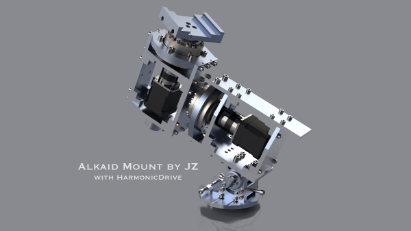
 for anything to be seen at all, through the noise. But, this ball of rock we sit on is rotating constantly, so the only solution is to track the object of interest, to compensate. This is referred to as equatorial tracking, and allows the rotation of the Earth to be compensated for during a long exposure.


