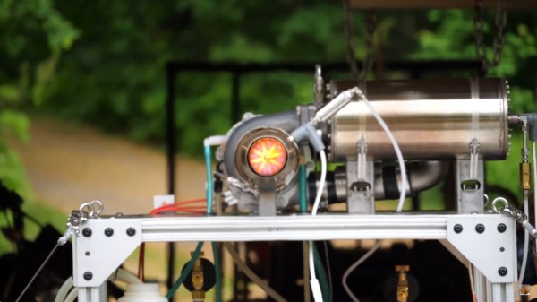
FFT display on 16x16 RGB LED grid

Art Project Fast And Fouriously Transforms Audio Into Eye Candy

Fast Fourier Transforms. Spectrum Analyzers. Waterfall displays. Not long ago, such terms were reserved for high end test gear. But oh, how things have changed! It’s no surprise to many Hackaday readers that modern microcontrollers have transformed the scene as they become more powerful and as a result are endowed with more and more powerful software libraries. [mircemk] has used such a library along with other open source software combined with mostly off the shelf hardware to create what he calls the DIY FFT Spectrum Analyzer. Rather than being a piece of test gear, this artful project aims to please the eye.

The overall build is relatively simple. Audio is acquired via a line-in jack or a microphone, and then piped into an ESP32. The ESP32 runs the audio through the FFT routine, sampling, slicing, and dicing the audio into 16 individual bands. The visual output is displayed on a 16 x 16 WS2812 Led Matrix. [mircemk] wrote several routines for displaying the incoming audio, with a waterfall, a graph, and other visualizations that are quit aesthetically pleasing. Some of them are downright mesmerizing! You can see the results in the video below the break.

Of course the build doesn’t stop with slapping some hardware and a few passive components together. To really be finished, it needs to be encased in something worth displaying. [mircemk] does not disappoint, as a beautiful 3D-printed enclosure wraps it all up nicely.

We think that the final product is great, and it reminds us of some of the very things that inspired us early on in our hacking careers. We would love to see this project integrated with an Interactive Musical Art Installation of any kind, the more esoteric the better. Perhaps a 555 timer synth could fit the bill? Be sure to share your own hacks with us via the Tip Line!

Continue reading “Art Project Fast And Fouriously Transforms Audio Into Eye Candy”

The Compute Module Comes Of Age: Say Hello To The Real Cutting Edge Of Raspberry Pi

If we wanted to point to an epoch-making moment for our community, we’d take you back to February 29th, 2012. It was that day on which a small outfit in Cambridge put on the market the first batch of their new product. That outfit was what would become the Raspberry Pi Foundation, and the product was a run of 10,000 Chinese made versions of their very first single board computer, the Raspberry Pi Model B. With its BCM2835 SoC and 512 megabytes of memory it might not have been the first board that could run a Linux distribution from an SD card, but it was certainly the first that did so for pocket money prices. On that morning back in 2012 the unforseen demand for the new board brought down the websites of both the electronics distributors putting it on sale, and a now-legendary product was born. We’re now on version 4 of the Model B with specs upgraded in almost every sense, and something closer to the original can still be bought in the form of its svelte stablemate, the Pi Zero.

How Do You Evolve Without Casualties?

The original Pi Model B+ from 2014.
The original Pi Model B+ from 2014. The form factor has had a few minor changes, but hardware-wise the Pi 4 follows this pretty closely. Lucasbosch, CC BY-SA 3.0.

The problem with having spawned such a successful product line is this: with so many competitors and copies snapping at your heels, how do you improve upon it? It’s fair to say that sometimes its competitors have produced more capable hardware than the Pi of the moment, but they do so without the board from Cambridge’s ace in the hole: its uniquely well-supported Linux distribution, Raspberry Pi OS. It’s that combination of a powerful board and an operating system with the minimum of shocks and surprises that still makes the Pi the one to go for after all these years.

Continue reading “The Compute Module Comes Of Age: Say Hello To The Real Cutting Edge Of Raspberry Pi”

3D Printing Toothpaste In The Name Of Science

While we don’t often see them in the hobbyist community, 3D printers that can extrude gels and viscous liquids have existed commercially for years, and are increasingly used for biological research. [Ahron Wayne] has recently been working with such a printer as part of a project to develop a printed wound dressing made of honey and blood clotting proteins, but for practice purposes, wanted to find a cheaper and more common material that had similar extrusion properties.

The material he settled on ended up being common toothpaste. In the video below you can see him loading up the cartridge of a CELLINK INKREDIBLE+ bioprinter with the minty goop, which is then extruded through a thin blunt-tip needle by compressed air. After printing out various shapes and words using the material, often times directly onto the bristles of a toothbrush, he’s come up with a list of tips for printing similarly viscous substances.

First and foremost, go slow. [Ahron] says the material needs a moment to contract after being extruded if it’s going to have any hope of supporting the next layer of the print. Thick layer heights are a necessity, as is avoiding sharp curves in your design. He also notes that overhangs must be avoided, and though it probably goes without saying, clarifies that an object printed from toothpaste will never be able to support anything more than its own weight.

In addition to the handful of legitimate DIY bioprinters that have graced these pages over the years, we’ve seen the occasional chocolate 3D printer that operated on a similar principle to produce bespoke treats, so the lessons learned by [Ahron] aren’t completely lost on the hacker and maker crowd. Who knows? Perhaps you’ll one day find yourself consulting this video when trying to get a modified 3D printer to lay down some soldering paste.

Continue reading “3D Printing Toothpaste In The Name Of Science”

A Deep Dive Into The Sound Of An Apple II

A major part of the retrocomputing scene for many of us lies in the world of chiptunes, music created either using original retrocomputing hardware or in the style of those early synthesiser chips. There’s one machine we don’t hear much about among all this though, and that’s the Apple II. Though probably one of the most expandable of all the 8-bit home computers, it lacked a sound channel beyond a speaker hooked up to a memory location port so any complex sound work had to be done via an add-on card. It’s something [Nicole Branagan] has investigated in depth, as she demonstrates first the buzz from the speaker and then what must have been an object of extreme desire back in the day, a Mockingboard sound card.

Her card is not an original but a modern recreation using the same hardware, which is to say a pair of 6522 VIA port chips, each driving an AY-3-8910 audio chip. This is already a familiar device to those who have heard an Amstrad CPC, a later Sinclair Spectrum or, an MSX, and in the Apple it delivers an impressive stereo sound thanks to both channels being present. Interestingly though, it delivers a far smoother output than an MSX playing the same music, probably because of a superior filtering circuit.

She wraps up with a discussion of coding on the Apple for the AY, and how to best accommodate the card on the later Apple IIgs. If the AY chip catches your interest, it’s also easy to drive from a microcontroller.

Spilled OJ Does A Number On Zelda Game Boy Cartridge

When [Taylor Burley] first opened up the cartridge for The Legend of Zelda: Oracle of Seasons, it certainly didn’t look like it had been dunked in corrosive orange juice. But looks can be deceiving, and while the game’s owner certainly did an admirable job of cleaning up the surface of the PCB, the cartridge was no longer functional. Clearly, this was a sticky situation.

After removing all of the components from the PCB, [Taylor] was quickly able to piece together what had happened. Despite the vigorous cleaning the game received after the spill, juice had found its way under each IC on the board. Left to sit in these nooks and crannies for who knows how long, the juice started to eat away at the traces on the PCB. Getting the game back up and running would naturally require considerable board repairs, but they don’t call him Solderking for nothing.

Corrosion lurking under each chip.

In the video below, you can see [Taylor] methodically scraping away the corrosion on the board before he starts recreating damaged connections with solid 30 gauge wire. Using tweezers and viewing the action through a digital microscope, he deftly bends the wire around to fit the shapes of the original traces and tacks the new conductors down with solder. He even goes ahead and repairs the traces that go to various test points on the cartridge; it’s a completely unnecessary extravagance, but we’re certainly not complaining. There’s a relaxing quality to watching him work, so we were in no rush to see his latest video end.

After fixing the board back up, he replaces all the components and takes it for a test drive on an original Game Boy Color. Confirming that Link’s 2001 outing is working as expected, he finishes the job with a few coats of spray-on conformal coating. With any luck, the next time this particular cartridge has to go face-to-face with some spilled juice, it will roll right off.

This isn’t the first time we’ve seen [Taylor] laboriously rebuild a Game Boy cartridge, and it certainly isn’t the first time we’ve seen him pull off some particularly impressive feats of soldering, either. His work always reminds us that patience and a steady hand can really do wonders.

Continue reading “Spilled OJ Does A Number On Zelda Game Boy Cartridge”

Solar Power Goes Back To 1910 Tech

If you want to read about a low-tech approach to solar cells invented — and forgotten — 40 years before Bell Labs announced the first practical silicon solar cell, we can’t promise the website, Low Tech Magazine, will be available. Apparently the webserver it is on is solar-powered, and a disclaimer mentions that it sometimes goes offline.

The article by [Kris De Decker] tells of George Cove and includes a picture from 1910 of the inventor standing next to what looks suspiciously like a solar panel (the picture above is from a 1909 issue of Technical World Magazine). His first demonstration of the technology was in 1905 and there is a picture of another device from 1909 that produced 45 watts of power using 1.5 square meters with a conversion efficiency of 2.75%. That same year, a new prototype had 4.5 square meters and used its 240-watt output to charge 5 lead-acid batteries. The efficiency was about 5%.

Continue reading “Solar Power Goes Back To 1910 Tech”

PCB sitting inside a 3D printed holder job, with holes to apply vacuum

Solder Paste Stencilling That Doesn’t Suck

Working with solder paste stencils can be a real faff, they rarely sit flat and move around when you so much as breath on them. [Unexpected Maker] airs his frustrations, and comes up with a simple solution, he simply makes a 3D-printed jig to align the PCB panel and applies his shop vacuum cleaner and hey presto!

If you’re ever been tempted to switch from frameless to framed solder stencils, then you’ll notice they can be rather awkward to work with. The usual online vendors have plenty of listings for stencil frame holders, but they do all seem to us, exactly the same, and more suited to stencilling T-shirts, than working with tiny PCB footprints.

The problem with unframed stencils is one of clamping and registration to the PCB, which framed stencils fix, when used with a jig that can dial in the rotation and translation errors.

But problem with those is, unless you have a perfectly flat support region all round the PCB, the weight of the frame tends to make the stencil bow up over the PCB, causing parts of it to lift away from the solder lands. This results in paste not being pushed into the places you want it, and instead it sticks to the stencil apertures and comes away when you lift it up. Most irritating.

You can try offset it by taping spare PCBs of the same thickness all around, but this is not always terribly successful in this scribe’s extensive experience doing this job by hand. [Unexpected Maker] solves this bowing issue by making a 3D printed jig that bolts to the stencil holder, takes a custom top plate with holes in, which in turns allows a vacuum to be applied from below. This sucks the PCB down to the jig, keeping it flat (in case it is also warped) and also pulls the stencil plate directly down to the PCB, making it also lie perfectly flat.

Continue reading “Solder Paste Stencilling That Doesn’t Suck”