It’s Always Pizza O’Clock With This AI-Powered Timepiece

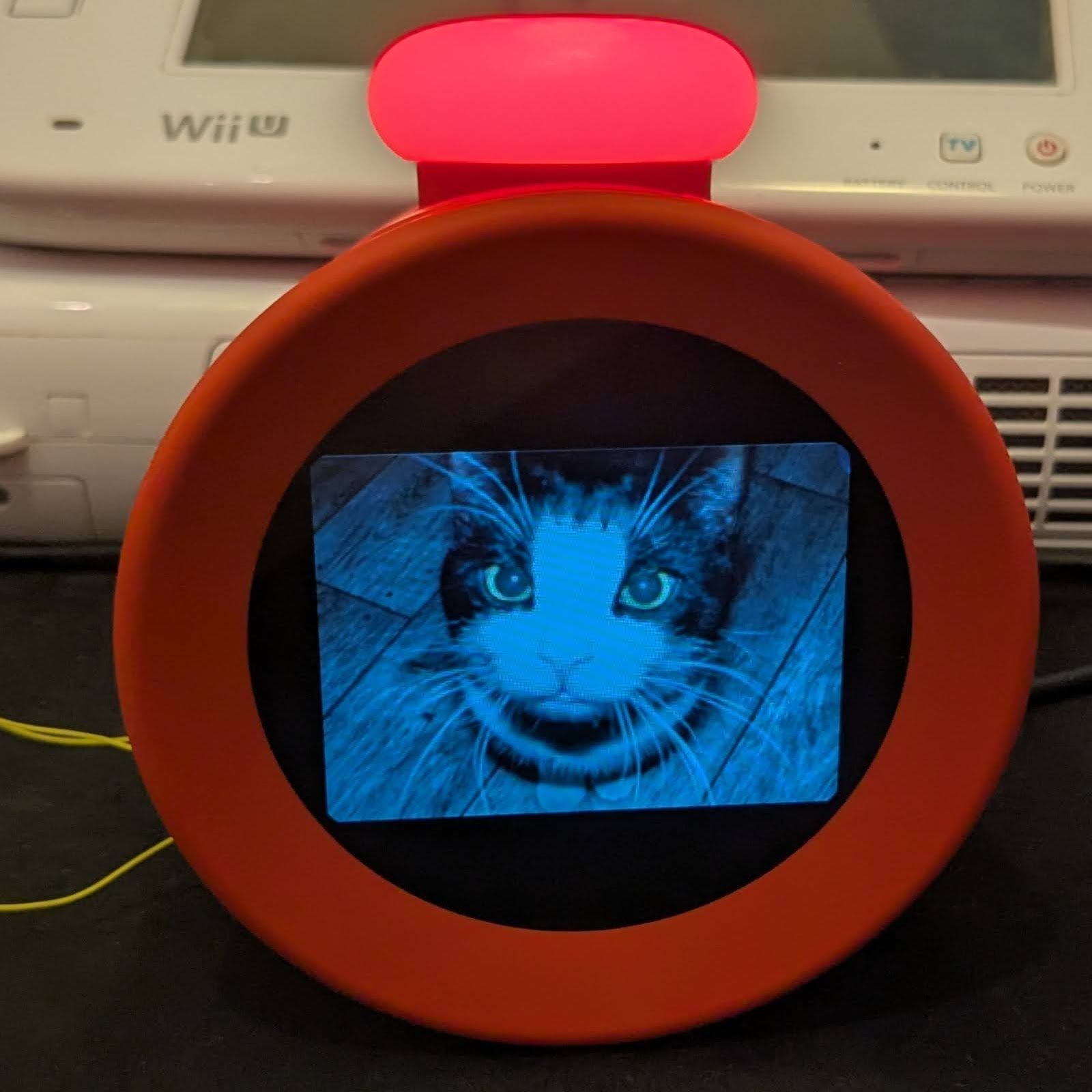
Right up front, we’ll say that [likeablob]’s pizza-faced clock gives us mixed feelings about our AI-powered future. On the one hand, if that’s Stable Diffusion’s idea of what a pizza looks like, then it should be pretty easy to slip the virtual chains these algorithms no doubt have in store for us. Then again, if they do manage to snare us and this ends up on the menu, we’ll pray for a mercifully quick end to the suffering.

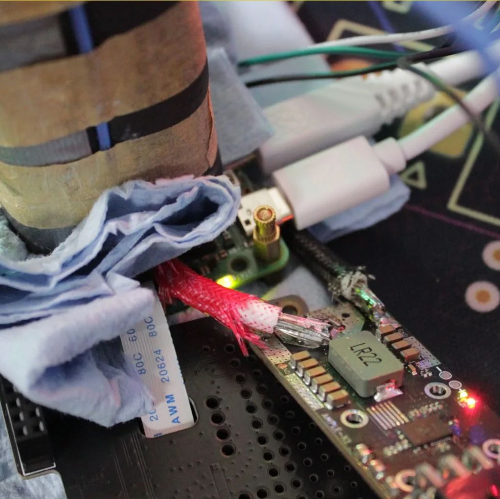
The idea is pretty simple; the clock’s face is an empty pizza pan that fills with pretend pizza as the day builds to noon, whereupon pizza is removed until midnight when the whole thing starts again. The pizza images are generated by a two-stage algorithm using Stable Diffusion 1.5, and tend to favor suspiciously uncooked whole basil sprigs along with weird pepperoni slices and Dali-esque globs of cheese. Everything runs on a Raspberry Pi Zero W, with the results displayed on a 4″ diameter LCD with an HDMI adapter. Alternatively, you can just hit the web app and have a pizza clock on your desktop. If pizza isn’t your thing, fear not — other food and non-food images are possible, limited only by Stable Diffusion’s apparently quite limited imagination.

As clocks go, this one is pretty unique. But we’re used to seeing unusual clocks around here, from another food-centric timepiece to a clock that knits.

Gimbal Clock Relies On Servos For Its Cool Movements

In the annals of human history, clocks got boring there for a while. Most were just variations on hands spinning in a circle, with the occasional tweeting bird mechanism to liven things up. These days, we’re treated to all kinds of original and oddball designs, like this neat gimbal clock from [Twisted&Tinned].

The concept of the build is straightforward enough. It has four main vertical arms, each with a servo at the base that rotates about a vertical axis. Upon each arm are between one and three servos which rotate 3D printed structures in the shape of numbers. A Wemos D1 Mini microcontroller commands the servos to the correct positions to display the current time. It also uses its WiFi connection to get accurate time updates directly from a network time server.

It’s quite an artistic build—and it’s rather enjoyable to watch this one flex and twist its way into displaying the right time. It’s also easier to read at a glance than some of the more unintelligible designs out there. Indeed, we see all kinds of neat and innovative clocks around these parts.

Continue reading “Gimbal Clock Relies On Servos For Its Cool Movements”

LED Wall Clock Gets Raspberry Pi Pico Upgrade

When [Rodrigo Feliciano] realized that the reason his seven-segment LED wall clock wasn’t working was because the original TG1508D5V5 controller was fried, he had a decision to make. He could either chuck the whole thing, or put in the effort to reverse engineer how the displays were driven and replace the dead controller with something a bit more modern. Since you’re reading this post on Hackaday, we bet you can guess which route he decided to take.

If you happen to own the same model of clock as [Rodrigo], then you really lucked out. He’s done a fantastic job documenting how he swapped the original controller out for a Raspberry Pi Pico W, which not only let him bring the clock back to life, but let him add new capabilities such as automatic time setting via Network Time Protocol (NTP).

But even if you don’t have this particular clock there’s probably something you can learn from this project, as it’s a great example of practical reverse engineering. By loading a high-resolution image of the back of the PCB into KiCad, [Rodrigo] was able to place all the components into their correct positions and following traces to see what’s connected to what.

Pretty soon he not only had a 3D model of the clock’s PCB, but a schematic he could use to help wire in the Pi Pico. Admittedly this is a pretty straightforward PCB to try and reverse engineer, but hey, you have to start somewhere.

We had high hopes for KiCad’s image import feature when it was introduced, and it’s great to see real-world examples like this trickle in as more folks learn about it.

Continue reading “LED Wall Clock Gets Raspberry Pi Pico Upgrade”

FallingWater Clock Puts New Spin On A Common LCD

Sometimes, all it takes is looking at an existing piece of tech in a new way to come up with something unique. That’s the whole idea behind FallingWater, a gorgeous Art Deco inspired clock created by [Mark Wilson] — while the vertical LCD might look like some wild custom component, it’s simply a common DM8BA10 display module that’s been rotated 90 degrees.

As demonstrated in the video below, by turning the LCD on its side, [Mark] is able to produce some visually striking animations. At the same time the display is still perfectly capable of showing letters and numbers, albeit in a single column and with noticeably wider characters.

In another application it might look odd, but when combined with the “sunburst” style enclosure, it really comes together. Speaking of the enclosure, [Mark] used OpenSCAD to visualize the five layer stack-up, which was then recreated in Inkscape so it could ultimately be laser-cut from acrylic.

Rounding out the build is a “Leonardo Tiny” ATmega32U4 board, a DS3221 real-time clock (RTC), a couple of pushbuttons, and a light dependent resistor (LDR) used to dim the display when the ambient light level is low. All of the electronics are housed on a small custom PCB, making for a nicely compact package.

This build is as simple as it is stylish, and we wouldn’t be surprised if it inspired more than a few clones. At the time of writing, [Mark] hadn’t published the source code for the ATmega, but he has provided the code to generate the cut files for the enclosure, as well as the Gerber files for the PCB. If you come up with your own version of this retro-futuristic timepiece, let us know.

Continue reading “FallingWater Clock Puts New Spin On A Common LCD”

Gloriously Impractical: Overclocking The Raspberry Pi 5 To 3.6 GHz

The Raspberry Pi 5 board strapped to a liquid nitrogen cooler and with ElmorLabs AMPLE-X1 power board attached. (Credit: Pieter-Jan Plaisier, SkatterBencher.com)
The Raspberry Pi 5 board strapped to a liquid nitrogen cooler with an ElmorLabs AMPLE-X1 power board attached. (Credit: Pieter-Jan Plaisier, SkatterBencher.com)

As impractical as most overclocking of computers is these days, there is still a lot of fun to be had along the way. Case in point being [Pieter-Jan Plaisier]’s recent liquid nitrogen-aided overclocking of an unsuspecting Raspberry Pi 5 and its BCM2712 SoC. Previous OCing attempts with air cooling by [Pieter] had left things off at a paltry 3 GHz from the default 2.4 GHz, with the power management IC (PMIC) circuitry on the SBC turning out to be the main limiting factor.

The main change here was thus to go for liquid nitrogen (LN2) cooling, with a small chipset LN2 pot to fit on the SBC. Another improvement was the application of a NUMA (non-uniform memory addressing) patch to force the BCM2712’s memory controller to utilize better RAM chip parallelism.

With these changes, the OC could now hit 3.6 GHz, but at 3.7 GHz, the system would always crash. It was time to further investigate the PMIC issues.

The PMIC imposes voltage configuration limitations and turns the system off at high power consumption levels. A solution there was to replace said circuitry with an ElmorLabs AMPLE-X1 power supply and definitively void the SBC’s warranty. This involves removing inductors and removing solder mask to attach the external power wires. Yet even with these changes, the SoC frequency had trouble scaling, which is why an external clock board was used to replace the 54 MHz oscillator on the PCB. Unfortunately, this also failed to improve the final overclock.

We covered the ease of OCing to 3 GHz previously, and no doubt some of us are wondering whether the new SoC stepping may OC better. Regardless, if you want to get a faster small system without jumping through all those hoops, there are definitely better (and cheaper) options. But you do miss out on the fun of refilling the LN2 pot every couple of minutes.

Thanks to [Stephen Walters] for the tip.

Tearing Down Nintendo’s Alarmo Alarm Clock

All your Nintendo Alarmo are belong to mew~ (Credit: GaryOderNichts, Blogspot)

Most of us will probably have seen Nintendo’s latest gadget pop up recently. Rather than a Switch 2 announcement, we got greeted with a Nintendo-branded alarm clock. Featuring a 2.8″ color LCD and a range of sensors, it can detect and respond to a user, and even work as an alarm clock for the low, low price of €99. All of which takes the form of Nintendo-themed characters alongside some mini-games. Naturally this has led people like [Gary] to buy one to see just how hackable these alarm clocks are.

As can be expected from a ‘smart’ alarm clock it has 2.4 GHz WiFi connectivity for firmware and content download, as well as a 24 GHz millimeter wave presence sensor. Before [Gary] even had received his Alarmo, others had already torn into their unit, uncovering the main MCU (STM32H730ZBI6) alongside a 4 GB eMMC IC, as well as the MCU’s SWD pads on the PCB. This gave [Gary] a quick start with reverse-engineering, though of course the MCU was protected (readout protection, or RDP) against firmware dumps, but the main firmware could be dumped from the eMMC without issues.

After this [Gary] had a heap of fun decrypting the firmware, which seems to always get loaded into the external octal SPI RAM before execution, as per the boot sequence (see featured image). This boot sequence offers a few possibilities for inserting one’s own (properly signed) contents. As it turns out via the USB route arbitrary firmware binaries can be loaded, which provided a backdoor to defeat RDP. Unfortunately the MCU is further locked down with Secure Access Mode, which prevents dumping the firmware again.

So far firmware updates for the Alarmo have not nailed shut the USB backdoor, making further reverse-engineering quite easy for the time being. If you too wish to hack your Alarmo and maybe add some feline charm, you can check [Gary]’s GitHub project.

Clockwork Derby gameboard

Clockwork Derby: Digital Robo Rally, Steampunk Style

Inspired by the classic game Robo Rally, [Ytec3D]’s Clockwork Derby takes tabletop gaming to the next level by combining steampunk aesthetics with automation. We recently had the chance to see it live at Hackfest, together with [Ytec3D]’s animatronic tentacle, and we can say that his new take on playful robotics offers a unique experience for game enthusiasts. The 300×420 mm board uses magnets, motors, and card readers to handle up to eight players, creating a smooth, automated version of Robo Rally where players can focus on strategy while the board handles movement.

In Clockwork Derby, game pieces are moved by a magnetic system controlled by the board, which rotates and shifts pieces in real-time. Each player uses a card reader to program moves, with up to five cards per round. The board scans these cards via barcode scanners, so you don’t have to worry about tracking your moves or adjusting game pieces manually. [Ytec3D]’s game rules have been optimized for the automated setup, allowing for smoother gameplay and an emphasis on strategic choices.

The project is a standout for hackers and tinkerers who appreciate blending physical mechanics with digital precision. It’s a great example of how classic games can be modernized with a bit of ingenuity and tech. For those interested in DIY gaming projects or automation, Clockwork Derby is definitely worth exploring. To dive deeper into the build details and see more of the project, visit [Ytec3D]’s project page for an in-person look at this inventive tabletop game!

Continue reading Clockwork Derby: Digital Robo Rally, Steampunk Style”