Typically, electric skateboards drive one or more wheels with brushless motors, while keeping everything mounted on otherwise fairly-standard trucks to maintain maneuverability. However, [swedishFeetballs] decided to go a different route, building a 3-wheeled design using some interesting parts.
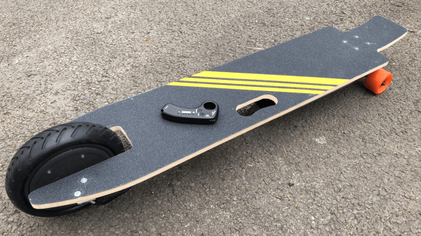
The build relies on a large combined hub motor and wheel, similar to those you would find on a hoverboard or some electric scooters; this one is a Xiaomi part sourced from eBay. It’s controlled via an off-the-shelf electric skateboard speed controller that comes complete with its own remote.
The hardware is all bolted up to a custom skateboard deck built from scratch to accept the large single rear wheel. Up front, a regular skateboard truck is used. Batteries are mounted under the deck. Reportedly, the board has a top speed of 15 mph, which unsurprisingly matches that of the Xiaomi M365 the hub motor is sourced from.
It’s a neat way to build an electric skateboard, and to be honest we couldn’t be more curious as to how it rides. Unfortunately, only a few seconds of footage is available, but we’ve embedded it below for your watching pleasure!
Meanwhile, you might also be curious as to the benefits of a half-track skateboard. Video after the break.
Continue reading “3-Wheeled Electric Skateboard Does Things Differently”