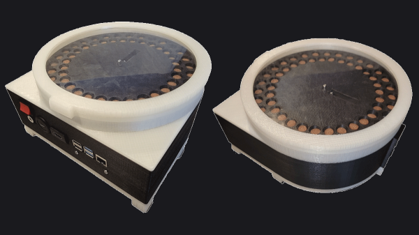
Hacking A PIC To Redefine A Microphone’s Transmit Frequency

Software defined radio and widespread software-controlled PLL synthesis for RF has been a game changer. Things like the RTL-SDR can be any kind of radio you like on almost any frequency you like. But not every SDR or PLL system opens the configuration doors to you, the end user. That was the problem [vgnotepad] faced when trying to connect a Sennheiser wireless microphone to some receivers. They didn’t use the same frequencies, even though the transmitter was programmable. The solution to that is obvious — hack the transmitter!

The post is only part one of several parts and if you read to the end, you’ll learn a lot about what’s inside the device and how to crack it. Luckily, the device uses a PIC processor, so getting to the software wasn’t a big issue.

Continue reading “Hacking A PIC To Redefine A Microphone’s Transmit Frequency”

The O’Scope Restoration

These days, a pretty nice oscilloscope can fit in your toolbox and even a “big” instrument is probably something you can tuck under your arm. But that hasn’t always been the case. Consider this old HP 150A, restored by [USagi Electric]. (Video, embedded below.)

The 10 MHz dual channel scope might not seem very high-tech today, but when HP rolled it out in the 1950s to challenge Tektronix, it was quite respectable. The $1,000 price tag just for the mainframe was pretty respectable, too. Unfortunately, the scope wasn’t very reliable with more than 50 tubes in it, and HP quickly had to develop new entries in the scope market.

Continue reading “The O’Scope Restoration”

Stereo Recording Made Easy With A 3D-Printed Mount

When making a recording it can be surprisingly difficult to capture a good stereo image. A well-known technique is the ORTF microphone arrangement in which two cardoid microphones sit at 110 degrees to each other and 17cm apart, and thus pick up a readily reproducible stereo separation. It’s something that we’ve been known to do in our student days with a pair of Shure SM58s and a stack of Post Office elastic bands, but [marsairforce] has done a much nicer job with a very neat 3D-printed microphone clip.

Designed in OpenSCAD, the first iteration printed on a resin printer proved to be too brittle for the task, so a second version was printed on an FDM machine. This incorporated significant strengthening, as well as a screw mount for a microphone stand. The result is an extremely useful and cheap addition to any recording set-up, and anyone who has wrestled with achieving a good stereo image will appreciate it. You can see some of what went into it in the video below the break.

If this is your field of interest, you might also wish to look at a binaural microphone.

Continue reading “Stereo Recording Made Easy With A 3D-Printed Mount”

An Epic Tale Of Reset Line Detective Work

The Pine64 folks have given us so many tasty pieces of hardware over the last few years, but it’s fair to say that their products are for experimenters rather than consumers and can thus be a little rough around the edges at times. Their Clusterboard for example is a Mini-ITX PCB which takes up to seven of their SOPINE A64 compute modules, and networks them for use as a cluster by means of an onboard Gigabit Ethernet switch. It’s a veritable powerhouse, but it has an annoying bug in that it appears reluctant to restart when told. [Eric Draken] embarked upon a quest to fix this problem, and while he got there in the end his progress makes for a long and engrossing read.

We journey through the guts of the board and along the way discover a lot about how reset signals are generated. The eventual culprit is a back-EMF generated through the reset distribution logic itself causing the low-pulled line to never quite descend into logic 0 territory once it has been pulled high, and the solution an extremely simple application of a diode. For anyone who wishes to learn about logic level detective work it’s well worth a look. Meanwhile the board itself with its 28 ARM cores appears to have plenty of potential. It’s even a board we’ve mentioned before, in a personal supercomputer project.

A Satellite Upconverter Need Not Be Impossible To Make

Those readers whose interests don’t lie in the world of amateur radio might have missed one of its firsts, for the last year or two amateurs have had their own geostationary satellite transponder. Called Es’hail-2 / AMSAT Phase 4-A / Qatar-OSCAR 100, it lies in the geostationary orbit at 25.9° East and has a transponder with a 2.4 GHz uplink and a 10.489 GHz downlink. Receiving the downlink is possible with an LNB designed for satellite TV, but for many hams the uplink presents a problem. Along comes [PY1SAN] from Brazil with a practical and surprisingly simple solution using a mixture of odd the shelf modules and a few hand-soldered parts.

An upconverter follows a simple enough principle, the radio signal is created at a lower frequency (in this case by a 435 MHz transmitter) and mixed with a signal from a local oscillator. A filter then picks out the mixer product — the sum of the two — and amplifies it for transmission. [PY1SAN]’s upconverter takes the output from the transmitter and feeds it through an attenuator to a MiniCircuits mixer module which takes its local oscillator via an amplifier from a signal generator module. The mixer output goes through a PCB stripline filter through another amplifier module to a power amplifier brick, and thence via a co-ax feeder to a dish-mounted helical antenna.

The whole thing is a series of modules joined by short SMA cables, and could probably be largely sourced from a single AliExpress order without too much in the way of expenditure. It’s by no means easy to get on air via Es’hail-2, but at least now it need not be impossibly expensive. Even the antenna can be made without breaking the bank.

We covered Es’hail-2 when it first appeared. May it long provide radio amateurs with the chance to operate worldwide with homebrew microwave equipment!

Continue reading “A Satellite Upconverter Need Not Be Impossible To Make”

Retrotechtacular: Mechanical TV From The People Who Made It Happen

If we have a television in 2021 the chances are that it will be a large LCD model, flat and widescreen, able to display HD images in stunning clarity. Before that we’d have had a CRT colour TV, them maybe our parents grew up with a monochrome model. Before those though came the first TVs of all, which were mechanical devices that relied on a spinning disk to both acquire and display the image. The BBC Archive recently shared a vintage clip from 1970 in which two of the assistants of [John Logie Baird], the inventor of the first demonstrable television system, demonstrated its various parts and revealed its inner workings.

We’ve covered the Nipkow scanning disk in a previous article, with its characteristic spiral of holes. We see the original Baird Televisor, but the interesting part comes as we move to the studio. Using the original equipment they show a dot of light traversing the presenter’s face to scan a picture before taking us to a mock-up of the original studio. Here there’s a surprise, because instead of the camera we’d expect today there is a Nipkow disk projector which traverses the subject sitting in the dark. A bank of photocells above the projector senses the reflected light, and returns a video signal.

The resulting low-resolution pictures had a low enough bandwidth to be broadcast over an AM radio transmitter, and for a tiny 30-line picture in the glowing pink of a neon light they provide a surprising amount of detail. With such a straightforward principle it’s not surprising that they’ve appeared in a few projects on these pages, including an Arduino driven colour video monitor, and a POV clock. Take a look at the video below the break.

Continue reading “Retrotechtacular: Mechanical TV From The People Who Made It Happen”

One Of The Largest Large Format Cameras You Will Ever Have Seen

When fate lands a very high quality lens in front of you, what do you do with it? If you are [Tim Hamilton], the solution is obvious. Use it in a huge large-format camera.

The lens came from a newspaper magnifier made redundant by digitalisation and used as a paperweight. It’s an extremely high quality piece of optical equipment so seeing it wasted in this way was a source of distress. So after characterising it an enormous scaled-up box and bellows was constructed, and set upon a suitably substantial wheeled tripod.

Instead of a huge piece of film or some unobtainable giant electronic sensor, the image is projected onto a large screen at the rear of the camera. A modern digital camera is mounted inside the box just beneath the lens and photographs the screen, resulting in the feel of the largest of large format cameras with the convenience of a digital format. The resulting images have a special quality to them that recalls pictures from the past, and definitely makes the camera a special if slightly inconvenient device.

This may be one of the larger cameras we’ve featured, but it’s not the first that uses a similar technique.