The analog computer of decades-gone-by is something many of us younger engineers never got the chance to experience first hand. It’s pretty much a case of reading about them on these fine pages or perhaps looking at a piece of one behind glass in one of the more interesting museums out there. But now, there is another option, (THAT) The Analog Thing. Developed by Berlin-based Analog computer-on-chip specialist Anabrid, THAT is an Open Source analog computer you can build yourself (eventually) or buy from them fully assembled. At least, that’s their plan.
From the 1970s onwards, digital computers became powerful enough to replace analog computers in pretty much every area, and with the increased accuracy this brought, the old analog beasts became obsolete overnight. Now, there seems to be a move to shift back a little, with hybridized analog-digital approaches looking good for some applications, especially where precision is not paramount. After all, that pile of fatty grey matter between your ears is essentially a big analog computer, and that’s pretty good at problem solving.
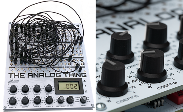
Looking over the project Wiki there are a few application examples and some explanatory notes. Schematics are shown, albeit only images for now. We can’t find the PCB files either, but the assembly instructions show many bodge wires, so we guess they’re re-spinning the PCB to apply fixes before releasing them properly. This is clearly work-in-progress and as they say on the main site, their focus is on chips for hybrid analog-digital computing, with a focus on energy-efficient approximate methods. With that in mind, we can forgive that the community-focused learning tools are still being worked on. All that said, this is still a very interesting project, and definitely would be a Christmas present this scribe would be more than happy to unwrap.
Continue reading “Forget Digital Computing, You Need An Analog Computer”