Hands On With The Raspberry Pi POE+ HAT

There’s a lot happening in the world of Pi. Just when we thought the Raspberry Pi Foundation were going to take a break, they announced a new PoE+ HAT (Hardware Attached on Top) for the Pi B3+ and Pi 4, and just as soon as preorders opened up I placed my order.

Now I know what you’re thinking, don’t we already have PoE HATs for the Pis that support it? Well yes, the Pi PoE HAT was released back in 2018, and while there were some problems with it, those issues got cleared up through a recall and minor redesign. Since then, we’ve all happily used those HATs to provide up to 2.5 amps at 5 volts to the Pi, with the caveat that the USB ports are limited to a combined 1.2 amps of current.

PoE vs PoE+
$20 for either of them. Choose wisely.

The Raspberry Pi 4 came along, and suddenly the board itself can pull over 7 watts at load. Combined with 6 watts of power for a hungry USB device or two, and we’ve exceeded the nominal 12.5 watt power budget. As a result, a handful of users that were trying to use the Pi 4 with POE were hitting power issues when powering something like dual SSD drives over USB. The obvious solution is to make the PoE HAT provide more power, but the original HAT was already at the limit of 802.3af PoE could provide, with a maximum power output of 12.95 watts.

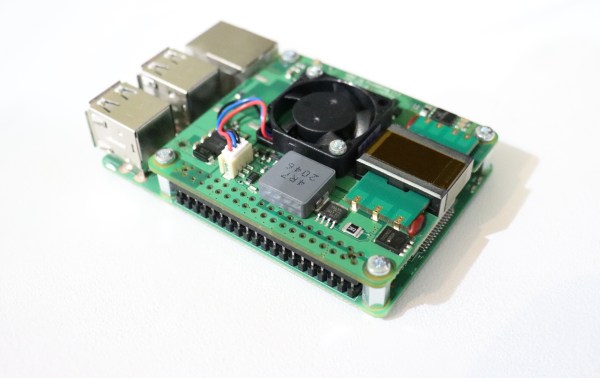
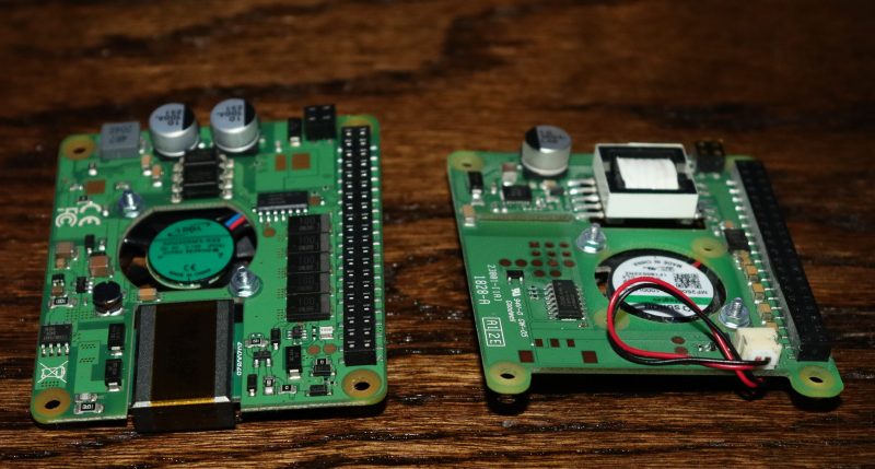
The solution the Raspberry Pi Foundation came up with was to produce a new product, the PoE+ HAT, and sell it along side the older HAT for the same $20. The common name for 802.3at is “PoE+”, which was designed specifically for higher power devices, maxing out at 30 watts. The PoE+ HAT is officially rated to output 20 watts of power, 5 volts at 4 amps. These are the output stats, so the efficiency numbers don’t count against your power budget, and neither does the built-in fan.

Continue reading “Hands On With The Raspberry Pi POE+ HAT”

Raspberry Pi Cameras Stand In For Stereo Microscope

Handling tiny surface mount components and inspecting PCBs is a lot easier with a nice stereo microscope, but because of their cost and bulk, most hobbyists have to do without. At best they might have a basic digital microscope, but with only one camera, they can only show a 2D image that’s not ideal for detail work.

The team behind [Stereo Ninja] hopes to improve on the situation by developing a stereoscopic vision system that puts tiny objects up on the big screen in three dimensions. Utilizing the Raspberry Pi Compute Module, a custom carrier board that enables the use of both MIPI CSI camera interfaces, and a 3D gaming monitor, their creation combines the capabilities of a traditional stereo microscope with the flexibility of a digital solution.

With two Raspberry Pi cameras suspended over the work area, and the addition of plenty of LED light, Stereo Ninja is able to generate the 3D image required by the monitor. While the camera’s don’t have the same magnification you’d get from a microscope, they’re good enough for enlarging SMD parts, and looking at a big screen monitor certainly beats hunching over the eyepiece of a traditional microscope. Especially if you’re trying to show something to a group of people, like at a hackerspace.

Of course, not everyone has a large 3D gaming monitor on their workbench. In fact, given how poorly the tech went over with consumers the last time it was pushed on us, we’d wager more hackers have stereo microscopes than 3D displays. Which is why the team’s next step is to have the Raspberry Pi generate the signals required by the shutter glasses, allowing Stereo Ninja to show a three dimensional image on 2D monitors; bringing this valuable capability to far larger audience than has previously been possible.

Continue reading “Raspberry Pi Cameras Stand In For Stereo Microscope”

A Custom Raspberry Pi Spotted In The Wild

Since the first Raspberry Pi came to market back in 2012 there have been a variety of models released. Some of them are rarer than others, and unusual boards can even be rather sought-after. This one spotted at a Thai junk vendor won’t be in the hands of many collectors though, and investigating it sheds a bit of light on some of the most unusual boards from the company.

The board is recognisably very similar to a Pi 3 with a BCM2837 SoC, but despite all that it has no Pi logo. On the underside there is an eMMC in place of the SD socket, and one pair of USB sockets has been replaced by a micro USB socket and a header. The source is reported to have been a washing machine, but given that this SoC is exclusive to the the Pi Foundation there’s no way it could easily have been manufactured by anyone else. The answer comes in the 2015 launch of a customisation service for industrial customers, which allowed manufacturers to have their own versions made of the fruity SBC.

From the point of view of an experimenter this board offers nothing that a standard device can’t do. But it’s an interesting glimpse of an unseen side to the Pi story, and it holds the prospect of other special versions being unearthed. If you find one on your travels, let us know!

Raspberry Pi Pico Oscilloscope

As you dive deeper into the world of electronics, a good oscilloscope quickly is an indispensable tool. However, for many use cases where you’re debugging low voltage, low speed circuits, that expensive oscilloscope is using only a fraction of its capabilities. As a minimalist alternative for these use cases [fhdm-dev] created Scoppy, a combination of firmware for the Raspberry Pi Pico and an Android app to create a functional oscilloscope.

As you would expect, the specifications are rather limited, capturing a maximum of 100 kpts at a speed of 500 kS/s shared between the two channels. Without some additional front end circuitry to protect the Pico, the input voltage is limited to 0-3.3 V. Neither the app nor the firmware is open source, and getting access to the second channel and removing ads requires a ~$3 in-app purchase. Even so, we can still think of plenty of practical uses for a ~$7 oscilloscope. If you do decide to add some front-end circuitry to change to voltage range, you can set them in the app, and switch between them by pulling certain GPIO pins high or low. The app has most of the basic oscilloscope features covered, continuous and single shot capture, adjustable trigger settings and a scalable waveform display.

Simple, cheap oscilloscopes like these have their place, but you start to understand why the “real” ones are so expensive when you see what goes into developing a high performance oscilloscope.

The Compromises Of Raspberry Pi Hardware Documentation

[Rowan Patterson] informed us about a recent ticket he opened over at the Raspberry Pi Documentation GitHub repository. He asked about the the lack of updates to the Raspberry Pi 4’s USB-C power schematics for this board. You may recall that the USB-C power issue was covered by us back in July of 2019, yet the current official  Raspberry Pi 4 schematics still show the flawed implementation, with the shorted CC pins, nearly two years later.

[Alasdair Allan], responsible for the Raspberry Pi  documentation, mentioned that they’re in the process of moving their documentation from Markdown to AsciiDoc, and said that they wouldn’t have time for new changes until that was done. But then [James Hughes], Principal Software Engineer at Raspberry Pi,  mentioned that the schematics may not be updated even after this change due to a of lack of manpower.

As [James] emphasized, their hardware will probably never be open, due to NDAs signed with Broadcom. The compromise solution has always been to publish limited peripheral schematics. Yet now even those limited schematics may not keep up with board revisions.

An easy fix for the Raspberry Pi 4’s schematics would be for someone in the community to reverse-engineer the exact changes made to the Raspberry Pi 4 board layout and mark these up in a revised schematic. This should be little more than the addition of a second 5.1 kΩ resistor, so that CC1 and CC2 each are connected to ground via their own resistor, instead of being shorted together.

Still, you might wish that Raspberry Pi would update the schematics for you, especially since they have updated versions internally. But the NDAs force them to duplicate their efforts, and at least right now that means that their public schematics do not reflect the reality of their hardware.

Raspberry Pi Floppy Driver Uncovers Fishy Secrets

A forum post by New Zealand electronics enthusiast [zl2wrw] about retreiving waypoints from a mysterious floppy disk caught our eye. The navigation system on his friend’s fishing boat had died and was replaced. But the old waypoints were stored on a 3-1/2 inch floppy disk that was unreadable on a normal PC. Not to be deterred, [zl2wrw] then looked for another solution — apparently a list of hot NZ fishing spots is worth quite the effort.

The tool he discovered, and the main point of this story, is the bbc-fdc by [Jasper Renow-Clarke] aka [picosonic]. [Jasper] made this project to read 5-1/4 inch Acorn DFS floppies from his BBC Micro. But bbc-fdc can be used to read a variety of floppy disk formats, such as DOS, C64, Apple II, and others It can also just capture raw magnetic flux transitions on the disk, blissfully unaware of any logical structure to the data. We recently wrote about another Raspberry Pi Floppy Drive Controller project by [Scott Baker]. What sets [picosonic]’s project apart is that he’s not using an FDC controller chip here. The only interface electronics is a couple of open-collector 7406 ICs. Data is read using the SPI peripheral. If you need to archive old floppy disks or do a forensic analysis of unknown disks like [zl2wrw], then one of these two projects will almost certainly do the trick.

Meanwhile back in New Zealand, [zl2wrw] discovered that the floppy format was standard (Modified Frequency Modulation, MFM) by examining the raw flux dump. However, the filesystem was a mystery — it didn’t quite match any of the usual suspects. So [zl2wrw] dug into the hex dump of the data and figured out enough of the structure to manually recover the waypoints. Subsequently, a user on the forum found a document describing the file system used by Furuno GPS units, which proved to be a close match albeit after the fact. Alas, [zl2wrw] hasn’t publish the coordinates of those good fishing spots.

Have you had any successes (or failures) when it comes to reading data from old disks? Or have you encountered peculiar disk formats and/or file systems, where having a tool like this could have been helpful? Let us know in the comments below.

Raspberry Pi Hat Adds SDR With High Speed Memory Access

An SDR add-on for the Raspberry Pi isn’t a new idea, but the open source cariboulite project looks like a great entry into the field. Even if you aren’t interested in radio, you might find the project’s use of a special high-bandwidth memory interface to the Pi interesting.

The interface in question is the poorly-documented SMI or Secondary Memory Interface. [Caribou Labs] helpfully provides links to others that did the work to figure out the interface along with code and a white paper. The result? Depending on the Pi, the SDR can exchange data at up to 500 Mbps with the processor. The SDR actually uses less than that, at about 128 Mbps. Still, it would be hard to ship that much data across using conventional means.

On the radio side, the SDR covers 389.5 to 510 MHz and 779 to 1,020 MHz. There’s also a wide tuning channel from 30 MHz to 6 GHz, with some exclusions. The board can transmit at about 14 dBm, depending on frequency and the receive noise figure is under 4.5 dB for the lower bands and less than 8 dB above 3,500 MHz. Of course, some Pis already have a radio, but not with this kind of capability. We’ve also seen SMI used to drive many LEDs.