In the 1850s British railway companies started introducing a single standard time to make their timetables consistent. Before that, every city would set its own clock based on the observation of the position of the sun. Nowadays, precise time standards are not only needed so people don’t miss their trains but also make modern communication technologies and satellite navigation work.
Generally, there are two methods of defining time, one is based on the local passage of time as measured by atomic clocks, while the other relies on the exact measurement of Earth’s rotation. The latter is not an easy exercise that involves extragalactic radio sources or huge laser-based gyroscopes. The constant survey of the Earth’s spin tells us that days are constantly getting longer, but surprisingly, severe earthquakes and weather phenomena can also take little discrete bites out of the planet’s supply of rotational kinetic energy.
How do we keep our ultra precisely measured time, the rotation of the Earth, and our position in the heavens in line?
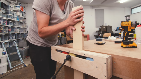
On the eternal quest of workshop upgrades, [Alexandre Chappel] has combined woodworking and 3D printing to add a versatile 0.5 m wide vise with some clever internals to his workbench.
The challenge with such a wide vise is that it requires two timed lead screws on either end of the vise to prevent if from pulling skew under force. This can be done with a chain, belt, or [Alexandre]’s choice, gears. Inside the moving part of the vise he fitted series of 5 herringbone gears. By turning the center gear with a lever, it rotates the gears on the end which are fixed to tow lead screws. The external surfaces of the clamp are made with plywood, and the gears are printed with PLA and high infill percentage. [Alexandre] does say that he is not sure durable the gears are, but they definitely aren’t flimsy. He added an acrylic inspection window to the box section, which we think looks superb with the colored gears peaking through. The back of the vise is mounted inside the workbench, which keeps the look clean and doesn’t take up any bench space.
[Alexandre] does a lot of filming in his workshop, so recently he also built a very impressive and practical camera arm to avoid having to move tripods the whole time. A vise is a must-have tool in almost any workshop, so we’ve seen a few DIY versions, like magnetic base vise and one with a hydraulic vise.
For just over sixteen years we’ve been publishing fresh hacks every day. We’ve just passed another milestone: the one millionth Hackaday comment was made just a few minutes ago.
A million of anything is impressive, but it’s not the sheer volume that’s on my mind today, but how time and again I’m gobsmacked by the insightful comments I find on these pages, and the people who put them there. We find leads for futures stories, answers to unknowns voiced in the articles, and have conversations with thousands of people whose paths we never would have crossed otherwise.
Not a week goes by that I don’t lose myself in a comment thread, usually taking me down the rabbit hole of exploring a bit of technology previously hidden to me but revealed by a few words. How many Hackaday articles were spawned by someone posting just the right link in the comment section?
Too often the people who moved the world with interesting technologies move through their careers and beyond without anyone to really tell their stories to, and those are some of the best stories from the people working with the tech on a daily basis for decades. But then we publish an article that puts a spotlight on their corner of knowledge and we get to hear how it was from their perspective. It’s so gratifying to get these moments of insight on who and what have kept humanity’s relay-race of science forward.
So thank you! Keep those comments and those stories coming!
When the Prusa i3 MK3 was released in 2017, it was marketed as being “bloody smart” thanks to the impressive number of sensors that had been packed into the printer. The update wasn’t really about improving print quality over the MK2, but rather to make the machine easier to use and more reliable. There was a system for resuming prints that had stopped during a power outage, a thermometer so the firmware could compensate against thermal drift in the inductive bed sensor, RPM detection on all of the cooling fans, and advanced Trinamic stepper drivers that could detect when the printer had slipped or gotten stuck.
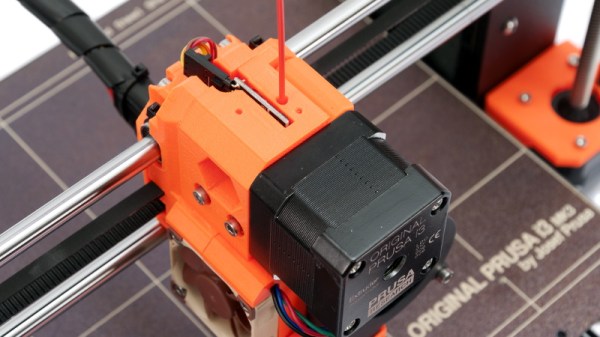
The optical filament sensor of the Prusa i3 MK3.
But the most exciting upgrade of all was the new filament sensor. Using an optical encoder similar to what you’d find in a mouse, the Prusa i3 MK3 could detect when filament had been inserted into the extruder. This allowed the firmware to pause the print if the filament had run out, a feature that before this point was largely unheard of on consumer-grade desktop 3D printers. More than that, the optical encoder could also detect whether or not the filament was actually moving through the extruder.
In theory, this meant the MK3 could sense problems such as a jammed extruder or a tangle in the filament path that was keeping the spool from unrolling. Any other consumer 3D printer on the market would simply continue merrily along, not realizing that it wasn’t actually extruding any plastic. But the MK3 would be able to see that the filament had stalled and alert the user. The capabilities of the optical filament sensor represented a minor revolution in desktop 3D printing, and combined with the rest of the instrumentation in the MK3, promised to all but eradicate the heartbreak of failed prints.
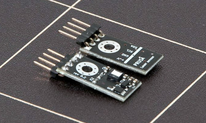
Fast forward to February of 2019, and the announcement of the Prusa i3 MK3S. This relatively minor refresh of the printer collected up all the incremental tweaks that had been made during the production of the MK3, and didn’t really add any new features. Though it did delete one: the MK3S removed the optical encoder sensor used in the MK3, and with it the ability to sense filament movement. Users would have to decide if keeping the ability to detect clogs and tangles was worth giving up all of the other improvements offered by the update.
But why? What happened in those three years that made Prusa Research decide to abandon what promised to be a huge usability improvement for their flagship product? The answer is an interesting look at how even the cleverest of engineering solutions don’t always work as expected in the real-world.
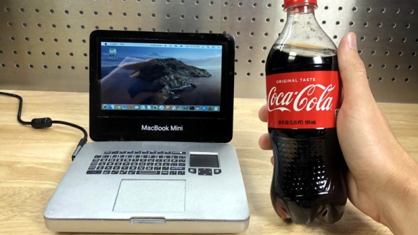
Getting the LCD panel and Raspberry Pi 4 to fit into the slim 3D printed case took considerable coaxing. In the video after the break, you can see [Michael] strip off any unnecessary components that would stand in his way. The LCD panel had to lose its speakers and buttons, and the Pi has had its Ethernet and USB ports removed. While space was limited, he did manage to squeeze an illuminated resin-printed Apple logo into the lid of the laptop to help sell the overall look.
The bottom half of the machine has a number of really nice details, like the fan grill cut from metal hardware cloth and a functional “MagSafe” connector made from a magnetic USB cable. The keyboard PCB and membrane was liberated from a commercially available unit, all [Michael] needed to do was model in the openings for the keys. Since the keyboard already came with its own little trackpad, the lower one is just there for looks.
Speaking of which, to really drive home the Apple aesthetic, [Michael] made the bold move of covering up all the screws with body filler after assembly. It’s not a technique we’d necessarily recommend, but gluing it shut would probably have made it even harder to get back into down the line.
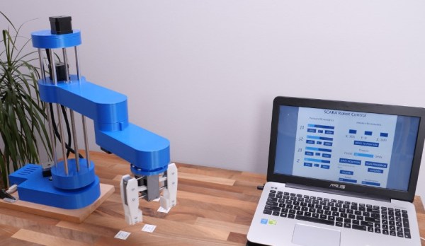
One of the side effects of the rise of 3D printers has been the increased availability and low cost of 3D printer components, which are use fill for range of applications. [How To Mechatronics] capitalized on this and built a SCARA robot arm using 3D-printed parts and common 3D-printer components.
The basic SCARA mechanism is a two-link arm, similar to a human arm. The end of the second joint can move through the XY-plane by rotating at the base and elbow of the mechanism. [How To Mechatronics] added Z-motion by moving the base of the first arm on four vertical linear rods with a lead screw. A combination of thrust bearings and ball bearings allow for smooth rotation of each of the joints, which are belt-driven with NEMA17 stepper motors. Each joint has a microswitch at a certain position in its rotation to give it a home position. The jaws of the gripper slide on two parallel linear rods, and are actuated with a servo. For controlling the motors, an Arduino Uno and CNC stepper shield was used.
The arm is operated from a computer with a GUI written in Processing, which sends instructions to the Arduino over serial. The GUI allows for both direct forward kinematic control of the joints, and inverse kinematic control, which will automatically move the gripper to a specified coordinate. The GUI can also save positions, and then string them together to do complete tasks autonomously.
The base joint is a bit wobbly due to the weight of the rest of the arm, but this could be fixed by using a frame to support it at the top as well. We really like the fact that commonly available components were used, and the link in the first paragraph has detailed instructions and source files for building your own. If the remaining backlash can be solved, it could be a decent light duty CNC platform, especially with the small footprint and large travel area. Continue reading “3D Printed SCARA Arm With 3D Printer Components”→
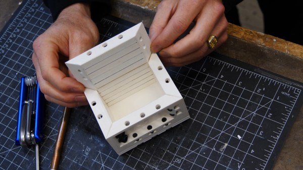
Prolific maker and product designer [Eric Strebel] has years of experience making reusable mold boxes for silicone and resin casting. He’s always used 3/4″ plywood before, but it comes with some problems such as inaccuracy, screws that eventually slip out, and no room at all for expansion. Now [Eric] has decided to devise a modular mold box system that’s so awesome, it’s even stack-able. Check out the design and build process in the video after the break.
[Eric] took advantage of additive manufacturing and made fancy trapezoidal walls with recessed bits that allow for the magic that this modular system hinges on — a handful of M6 socket cap screws and matching nuts for tensioning. Once the prints were ready, [Eric] pounded the nuts captive into the walls and marked fill lines every 10mm. As usual, [Eric]’s video comes with bonus nuggets of knowledge, like his use of a simple card scraper to clean up prints, smooth the sides, and chamfer all the edges.