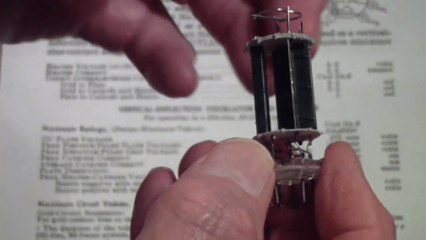
We see quite a bit of work where people decapsulate ICs or other solid state devices to expose their inner workings. But how about hollow state? [Tomtektest] had a dual triode that has lost its vacuum integrity — gone to air, as he calls it — and decided to open it up to better expose its inner workings. (Video, embedded below.)
Of course, you can always see the innards through the glass, but it is interesting to have the envelope out of the way. Apparently, how you remove the glass is a bit tricky if you don’t want to damage the working bits as you remove it.
In the beginning, there was hot glue. Plus some tape, and a not inconsiderable amount of Bondo. In general, building custom portable game consoles a decade or so in the past was just a bit…messier than it is today. But with all the incredible tools and techniques the individual hardware hacker now has at their disposal, modern examples are pushing the boundaries of DIY.
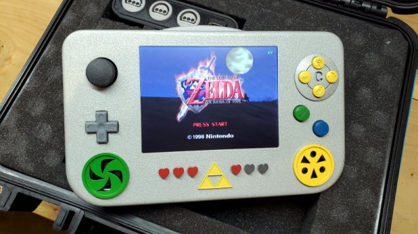
This Zelda: Ocarina of Time themed portable N64 by [Chris Downing] is a perfect example. While the device is using a legitimate N64 motherboard, nearly every other component has been designed and manufactured specifically for this application. The case has been FDM 3D printed on a Prusa i3, the highly-detailed buttons were printed in resin on a Form 3, and several support PCBs and interface components made the leap from digital designs to physical objects thanks to the services of OSH Park.
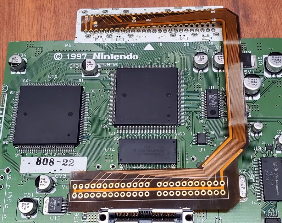
A custom made FFC to relocate the cartridge port.
Today, those details are becoming increasingly commonplace in the projects we see. But that’s sort of the point. In the video after the break, [Chris] breaks down the evolution of his portable consoles from hacked and glued together monstrosities (we mean that in the nicest way possible) to the sleek and professional examples like his latest N64 commission. But this isn’t a story of one maker’s personal journey through the ranks, it’s about the sort of techniques that have become available to the individual over the last decade.
Case in point, custom flexible flat cables (FFC). As [Chris] explains, when you wanted to relocate the cartridge slot on a portable console in the past, it usually involved tedious point-to-point wiring. Now, with the low-volume production capabilities offered by companies like OSH Park, you can have your own flexible cables made that are neater, faster to install, and far more reliable.
Projects like this one, along with other incredible creations from leaders in the community such as [GMan] are changing our perceptions of what a dedicated individual is capable of. There’s no way to be sure what the state-of-the-art will look like in another 5 or 10 years, but we’re certainly excited to find out.
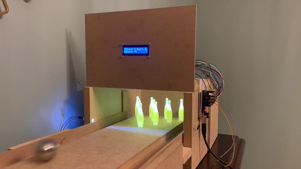
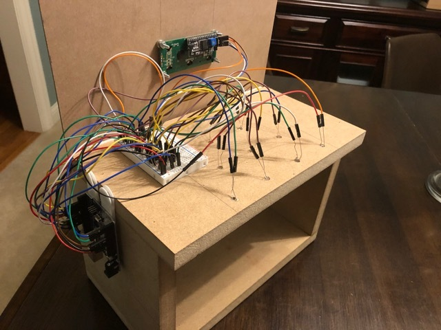
Bowling has been around since ancient Egypt and continues to entertain people of all ages, especially once they roll out the fog machine and hit the blacklights. But why pay all that money to don used shoes and drink watered-down beer? Just build a tabletop bowling alley in your spare time and you can bowl barefoot if you want.
Those glowing pins aren’t just for looks — the LEDs underneath them are part of the scoring system. Whenever a pin is knocked out of its countersunk hole, the LED underneath is exposed and shines its light on a corresponding light-dependent resistor positioned overhead. An Arduino Uno keeps track of of the frame, ball number, and score, and displays it on an LCD.
The lane is nearly six feet long, so this is more like medium-format bowling or maybe even skee-bowling. There are probably a number of things one could use for balls, but [lainealison] is using large ball bearings. Roll past the break to see it in action, but don’t go over the line!
We will admit that we often throw together software simulations of real-world things, but we’ll also admit they are usually quick and dirty and just dump out text that we might graph in a spreadsheet or using GNUPlot. But with Hash.ai, you can quickly generate simulations of just about anything quickly and easily. The simulations will have beautiful visualizations and graphs, too. The tool works with JavaScript or Python and you don’t have to waste your time writing the parts that don’t change.
The web-based tool works on the idea of agents. Each agent has one or more behaviors that run each time step. In the example simulation, which models wildfires in forests, the agent is named forest, although it really models one virtual tree. There’s also a behavior called forest which controls the tree’s rate of growth and chance of burning based on nearby trees and lightning. Other behaviors simulate a burning tree and what happens to a tree after burning — an ember — which may or may not grow back.
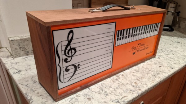
Way back in the 1970s, when smog laws were choking American V8s and the oil crisis was in full swing, Wurlitzer released their Key Note Visualizer. Intended as a teaching aid, the device lit up keys on a keyboard graphic, allowing an organ player to visually demonstrate their performance to a class. [Guy Dupont] set out to replicate this hardware, but with a modern twist.
The build consists of an ESP-32, which accepts MIDI data over Bluetooth Low Energy. This is then used to light up a series of RGB LEDs on a musical staff and a keyboard graphic, corresponding to the notes being played. The LEDs used are the old-school four-wire type, rather than more modern data-driven types. They’re placed in 3D-printed holders which serve to stop the light from each LED bleeding into adjacent areas. The faceplate is made of acrylic, stencilled with that classic orange paint and with vinyl decals applied for the markings. It’s all wrapped up in a walnut case, which [Guy] CNC machined himself.
It’s a tidy build that faithfully recreates the 1970s aesthetic of the original. We plaintively wish that manufacturers would release more electronics in walnut enclosures, though ask politely that they leave cheap veneer in the past where it belongs.
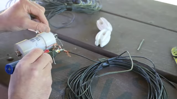
A dipole antenna is easy, right? Two wires, each a quarter wavelength long, emanate from a coax or other feedline. Unless it is an off-center dipole. The length is still the same, but you move the feed point to a different part. [KB9VBR] explains how this changes the antenna’s impedance from the nominal 70 ohms of a standard dipole.
Why would you want to do that? The trick is to find a feed point that has acceptable impedance on multiple ham radio bands. Most automatic tuners can handle a certain range of mismatch so using an antenna like this with a tuner can allow one antenna to serve multiple bands with no traps or switches.
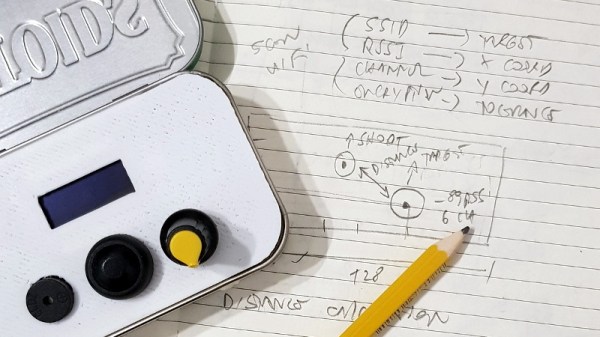
Looking for a way to make his warwalking sessions a bit more interactive, [Roni Bandini] has come up with an interesting way to gamify the discovery of new WiFi networks. Using a Heltec WiFi Kit 8, which integrates an OLED screen and ESP8266, this pocket-sized device picks up wireless networks and uses their signal strength and encryption type as elements of the game.
After selecting which network they want to play against, a target is placed on the screen. The distance between the target and the player is determined by signal strength, and how much damage the target can take correlates to how strong its encryption is. As you can see in the video after the break, gameplay is a bit reminiscent of Scorched Earth, where the player needs to adjust the angle of their artillery to hit distant targets.
The Heltec board is attached to a 3D printed front panel, which fits neatly into an Altoids tin. The controls consist of a button and a potentiometer, and with the addition of a battery pack salvaged from an old cell phone, this little device is ready to do battle wherever you roam.
While this is just a fun diversion for the time being, [Roni] says it wouldn’t take much to actual log networks to a file and generate some statistics about their strength and encryption type. If the idea of a portable WiFi scanning companion seems interesting, you should definitely check out the Pwnagotchi project.