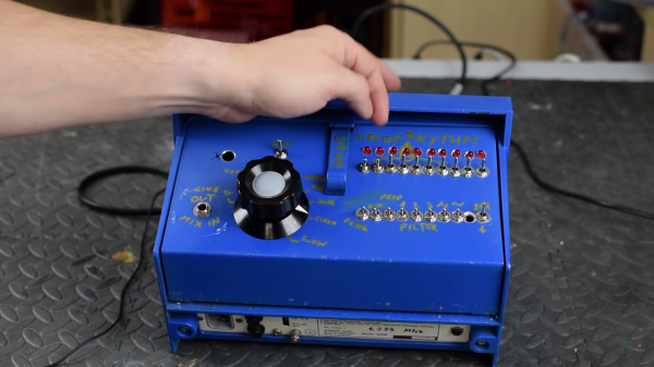
Bot Makes Etch A Sketch Art In One Continuous Line

Introduced in 1960 for the princely sum of $2.99 ($25.00 today), Etch A Sketch was to become a standard issue item for the Baby Boomers’ toy box. As enchanting as the toy seems, it’s hard to see why it had staying power: it was hard for young fingers to twirl the knobs, diagonal lines and smooth curves required a concert pianist’s fine motor control, and whatever drawings we managed to make were erased at the slightest jostle of the tablet.

Intent on righting these wrongs, [Sunny Balasubramanian] not only motorized an Etch A Sketch, but he’s also given it a mind of its own in a way. For those unfamiliar with the toy, it’s basically a manual X-Y plotter that drags a stylus across the underside of a glass screen, scraping off a silver powder clinging to the glass to make dark lines. Replacing the knobs with steppers is straightforward, of course, but driving them is the trick. [Sunny] hooked his up to a Raspberry Pi and wrote some Python code to drive them. The Pi also accepts input image files and processes them for rendering through the plotter, first doing Canny edge detection in OpenCV, then plotting a single path through the largest collection of connected pixels in the image. From there it’s just a matter of spinning the motors to create surprisingly detailed images. Check out the short video below to see it in action.

It’s hardly the first automatic Etch A Sketch we’ve seen – here’s one that automates everything including the shake to erase the drawing. That one cheats a little though, in that it rasters across the screen like a CRT. We really like how this one just does a single path. Pretty clever.

Continue reading “Bot Makes Etch A Sketch Art In One Continuous Line”

Gaze Upon This Daft Punk Helmet’s Rows Of Utterly Perfect Hand-Soldered LEDs

The iconic robot helmets of Daft Punk feature prominently as challenging DIY hardware projects in their own right, and the results never disappoint. But [Nathaniel Stepp]’s photo gallery of his own version really sets the bar in both quality and attention to detail. The helmet uses a Teensy 3.2 as the main processor, and the visor consists of 328 hand soldered through-hole APA106 addressable RGB LEDs. A laser cut panel serves as the frame for the LEDs, and it was heat-formed to curve around the helmet and mate into the surrounding frame. Each LED is meticulously hand-soldered, complete with its own surface mount decoupling cap; there’s no wasted space or excess wire anywhere to be seen. It looks as if a small 3D printed jig was used to align and solder the LEDs one or two columns at a time, which were then transferred to the visor for final connections with the power bus and its neighboring LEDs.

After the whole array was assembled and working, the back of each LED appears to have then been carefully coated in what looks like Plasti-Dip in order to block light, probably to minimize the blinding of the wearer. A small amount of space between each LED allows the eyeballs inside the helmet to see past the light show in the visor.

The perfectly done array of LEDs in the visor is just one of the design elements showing the incredible workmanship and detail in [Nathaniel]’s helmet. His website promises more build details are coming, but in the meantime you can drink in the details shown in the aforementioned photo gallery.

With Halloween approaching, you might be interested in rolling your own Daft Punk inspired helmet. Not ready to do everything from scratch? No problem, because it’s never been easier to make your own with the help of a 3D printer and some LED strips.

[via SparkFun Blog]

Give Yourself A Sixth Sense With An Arduino

If you carry a smartphone around in your pocket, you have a GPS navigation system, a compass, an altimeter, and a very powerful computer at your fingertips. It’s the greatest navigational device ever created. To use this sextant of the modern era you’ve got to look down at a screen. You need to carry a phone around with you. It’s just not natural.

For this entry into the Hackaday Prize, [Vojtech Pavlovsky] has an innovative solution to direction finding that will give you a sixth sense. It’s a headband that turns your temples into the input for a clever way to find yourself around the city or a forest, and it does it with just an Arduino and a few other bits.

The idea behind the Ariadne Headband is to create a haptic navigation system for blind people, runners, bikers, or really anybody. It does this by mounting four vibration motors on a headband, connecting those motors to an Arduino, sniffing data from a digital compass, and getting data over Bluetooth from an Android app.

All of these parts come together to form a new sense — a sense of direction. By simply telling the app to make sure you’re always oriented North, or to guide you along the grid of city streets, this headband becomes an inconspicuous and extraordinarily useful way to get around.

Retrotechtacular: Here’s How They Programmed The EDSAC Computer

When you write a program for your computer, whether it is a desktop machine, a microcontroller, or a supercomputer, the chances are that you use software tools to help you get the job done. High level languages, compilers, linkers, assemblers, debuggers, and code libraries have become so integrated that in many cases you will barely be aware of their existence. To all intents and purposes this huge toolchain will be the computer. But the first computer programmers had none of these luxuries. They had to hand assemble their own binaries, check them by hand, and debug them by guessing what had happened when they failed.

EDSAC I, 1948, W.Renwick with 5 hole tape reader and Creed teleprinter. Copyright Computer Laboratory, University of Cambridge. Reproduced by permission. [CC BY 2.0 UK]
EDSAC (Electronic delay storage automatic calculator) was the first computer operated by the University of Cambridge in the UK and one of the first few computers in the entire world when it was built in the late 1940s. It is the subject of the 1951 film you’ll find embedded below. Originally produced for a conference, the video sports a 1976 introduction and narration from the machine’s creator Professor Maurice Wilkes. It doesn’t take us through the design of the machine itself, instead it concentrates on the workflow required to program it.

The Paper-Heavy Process of Programming EDSAC

To illustrate the programming process, a committee of people who would now call themselves computer scientists, but probably then called themselves mathematicians, breaking a formula into subroutines before the code is laboriously hand assembled. The linking process is performed manually too by the secretary who types the code into a teletype for transfer to a punched tape. When a library function is required she reaches into a filing cabinet for the roll of tape containing it before running it through a tape duplicator to add it to the program. Finally the completed tape is checked and added to a job queue that consists of a row of hooks on the wall. Never complain that your toolchain is unwieldy again!

The original EDSAC was decommissioned in the late 1950s after serving the university and spawning a commercial version, the LEO, which became the first ever computer manufactured for use in commerce. That was not the end of the EDSAC story though, because in this century a team at the National Museum of Computing at Bletchley Park set about recreating EDSAC as an exhibit. And as luck would have it a member of that team was at the recent Electromagnetic Field hacker camp to give a talk about their work which you will also find below.

Building a Faithful Reproduction of EDSAC

Tony Abbey gives us both a history of the machine and a description of its architecture, followed by a run through their efforts in rebuilding it. You may be surprised by some of the unexpected facts from the talk. For instance, while all the tubes used in the EDSAC are still available, their bases are not. Equivalents were sourced from China, but team members had to modify them with dental drills.

They also needed to manufact the 1940s-style tube chassis, and the solution to that problem happened to be just down the road. Bletchley is part of modern-day Milton Keynes, a post-war new town that is also home to another famous name: Marshall amplifiers. Tube amps are built in a surprisingly similar way, so they took on the manufactured challenge. Not all the parts of the new EDSAC are original though. The memory used mercury delay lines in 1949, but for 2018 recreation the computer has a delay line using nickel wire and modern components. Tony admits that even that has caused problems, and there is a simulator using a microcontroller.

You can see the restored EDSAC at the National Museum of Computing. We visited it in 2016, and you can read our review. Meanwhile if you are an FPGA wizard, you can even have a virtual EDSAC of your own.

Continue reading “Retrotechtacular: Here’s How They Programmed The EDSAC Computer”

Maker Faire NY: Developing For The Final Frontier

The cost of getting a piece of hardware into space is now cheaper than ever, thanks in no small part to the rapid progress that’s been made by commercial launch providers such as SpaceX. In the near future, as more low-cost providers come online, it should get even cheaper. Within a few years, we could be seeing per kilogram costs to low Earth orbit that are 1/10th what they were on the Space Shuttle. To be sure, this is a very exciting time to be in the business of designing and building spacecraft.

But no matter how cheap launches to orbit get, it’ll never be cheaper than simply emailing some source code up to the International Space Station (ISS). With that in mind, there are several programs which offer students the closest thing to booking passage on a Falcon 9: the chance to develop software that can be run aboard the Station. At the 2018 World Maker Faire in New York we got a chance to get up close and personal with functional replicas of the hardware that’s already on orbit, known in space parlance as “ground units”.

On display was a replica of one of the SPHERES free-flying satellites that have been on the ISS since 2006. They are roughly the size of a soccer ball and utilize CO2 thrusters and ultrasonic sensors to move around inside of the Station. Designed by MIT as a way to study spaceflight techniques such as docking and navigation without the expense and risk of using a full scale vehicle, the SPHERES satellites are perhaps the only operational spacecraft to have never been exposed to space itself.

MIT now runs the annual “Zero Robotics” competition, which tasks middle and high school students with solving a specific challenge using the SPHERES satellites. Competitors run their programs on simulators until the finals, which are conducted using the real hardware on the ISS and live-streamed to schools.

We also saw hardware from “Quest for Space”, which is a company offering curricula for elementary through high school students which include not only the ground units, but training and technical support when and if the school decides to send the code to the matching hardware on the Station. For an additional fee, they will even work with the school to design, launch, and recover a custom hardware experiment.

Their standard hardware is based on off-the-shelf platforms such as Arduino and LEGO Mindstorms EV3, which makes for an easy transition for school’s existing STEM programs. The current hardware in orbit is setup for experiments dealing with heat absorption, humidity, and convection, but “Quest for Space” notes they change out the hardware every two years to provide different experiment opportunities.

Projects such as these, along with previous efforts such as the ArduSat, offer a unique way for the masses to connect with space in ways which would have been unthinkable before the turn of the 21st century. It’s still up for debate if anyone reading Hackaday in 2018 will personally get a chance to slip Earth’s surly bonds, but at least you can rest easy knowing your software bugs can hitch a ride off the planet.

Inductance In PCB Layout: The Good, The Bad, And The Fugly

When current flows through a conductor it becomes an inductor, when there is an inductor there is an electromagnetic field (EM). This can cause a variety of issues during PCB layout if you don’t plan properly, and sometimes we get burned even when we think we have planned for unwanted inductance and the effects that come with them.

When doing high speed logic we need to be able to deliver sudden changes in current to the devices if we want to have proper switching times and logic levels. Unfortunately inductance is usually not a friend in these circumstances as it resists those sudden changes in current. If the high speed devices are driving capacitive loads, which themselves are resisting changes in voltage, even more instantaneous current is needed.

Simply put, inductors resist a change of current, and can act as a low pass filter when in series with the signal or power supply flow. Inductors do this by storing energy in the flux surrounding the conductor. Alternatively capacitors resist a change in voltage (again by storing energy) and can act as a high pass filter when in series with the signal. This makes them a valuable tool in the fight against unwanted inductance in power supply distribution.

In the video below, and the remainder of this article, I’m going to dive into the concept of inductance and how it affects our design choices when laying out circuit boards.

Continue reading “Inductance In PCB Layout: The Good, The Bad, And The Fugly”

FPGA Jacked Into Pinball Machine Masters High Scores

How do you preserve high scores in an old arcade cabinet when disconnecting the power? Is it possible to inject new high scores into a pinball machine? It was the b-plot of an episode of Seinfield, so it has to be worth doing, leading [matthew venn] down the rabbit hole of FPGAs and memory maps to create new high scores in a pinball machine.

The machine in question for this experiment is Doctor Who from Williams, which, despite being a Doctor Who pinball machine isn’t that great of a machine. Still, daleks. This machine is powered by a Motorola 68B09E running at 2MHz, with 8kB of RAM at address 0x0000. This RAM backed up with a few AA batteries, and luckily is in a DIP socket, allowing [matthew] to fab a board loaded up with an FPGA development board that goes between the CPU and RAM.

The basic technique for intercepting and writing a new high score for this pinball machine comes from the incredible [sprite_tm] who is tweeting high scores from a 1943 cabinet. The idea is simple: just have an FPGA look at one specific memory address, and send some data to a computer when the data at that address is updated. For the Doctor Who pinball machine, this is slightly harder than it sounds: the data isn’t stored in hex, but packed BCD. After a little bit of work, though, [matthew] was able to write new high scores from a Python script running on a laptop. All the code (and a few more details) are over on a Github

Extending arcade games by tapping into address and data lines isn’t something we see a lot of, but it has been done, most famously with the Church of Robotron. Here, a few MAME hacks turn a game of Robotron into a Church for the faithful to fully commit themselves to the savior of the world, due to arrive in 66 years and save the remaining humans from the robot apocalypse. This hack of a Doctor Who pinball machine goes beyond a modded version of MAME, and if we’re ever going to make a real chapel with a real game of Robotron, these are the techniques we’re going to use.