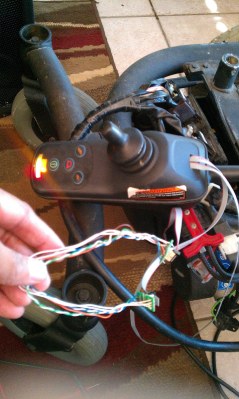
Wiring into the joystick is a quick and easy way to hack in custom control to a wheelchair.
Building robots can be fun, and remains a popular pastime among many in the hacker and maker set. However the hardware side of things can be daunting. This is particularly the case for those attempting to build something on a larger scale. A great shortcut is to start with a robust mechanical platform from the outset – and using an electric wheelchair is a great way to do so.
[Nikita] started this project way back in 2009, after finding a broken electric wheelchair at a flea market. It was no longer in fit condition for use as a wheelchair, so [Nikita] was able to score it for the low price of just $50. That’s a great price for a package which includes a robust chassis, wheels, motors and the required controllers to drive it all. With the platform in hand, it was time to get hacking.
Thus far, [Nikita] has gone so far as to strip the wheelchair of all extraneous parts, leaving it as a motorized carriage. Radio control has been implemented with the help of an Arduino, and a couple of “eyes” have been added to give it a little personality. It can also still be driven with the original joystick, which has been relocated on the chassis. Future plans involve adding a level of autonomy to allow the ‘bot to navigate waypoints and recognise faces, both tasks which should be significantly easier with 2019 technology. We’re eager to see where it goes next; we’ve seen great applications of wheelchair hardware before, after all. Video after the break.
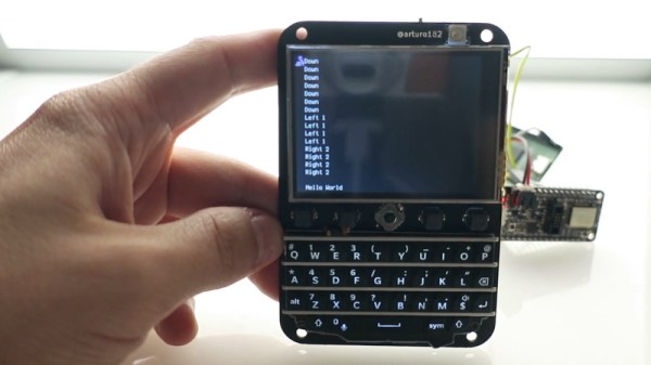
But recently creator [arturo182] wrote in to tell us that not only had all the parts arrived, but that he’d completed assembly of the first prototype. He even put together a video about the current status of the device, which you can see after the break. The short version is: it works, and it looks fantastic.
For those who might not have seen this project the first time around, the front features a 2.6 inch 320×240 touch screen display, four general purpose buttons, a RGB NeoPixel LED for visual status display, a five way joystick, and what’s arguably the star of the show, a QWERTY keyboard originally designed for the Blackberry Q10. Around the back it has an SD card slot, a socket for the Feather module of your choice, and some handy GPIO expansion pads you can attach your own hardware onto.
[arturo182] says he’s looking at a couple cosmetic changes, but on the whole, everything works and he considers the PCB essentially done. He’ll soon be sending out a handful of test units to individuals who’ve expressed interest in helping him develop the project and then…well, he’s not really sure what’s going to happen then. Some kind of commercial release seems like the logical conclusion given the interest he’s already seen in the project, but he hasn’t quite worked out whether that will be a kit or as assembled devices.
The features for this multimeter consist of voltage mode with a range of +/-6V and +/-60V. There’s a current mode, basically the same as voltage, with a range of +/-60 mA and +/-500mA. Unlike our bright yellow Fluke, there’s also a power mode that measures voltage and current at the same time, with all four combinations of ranges available. There’s a continuity test that sounds a buzzer when the resistance is below 50 Ω, and a component test mode that measures resistors, caps, and diodes. There’s a fully isolated USB interface capable of receiving commands and transmitting data, a real-time clock, and in the future there might be frequency measurement.
This build is based on the STM32F103 microcontroller, uses an old Nokia phone screen, and unlike so many other multimeters, this thing is small. It’s very small. More than small enough to fit in your pocket and forget about it, unlike nearly every other multimeter available. There’s one thing about multimeters, and it’s that the best multimeter is the one that you have in your hands when you need it, and this one certainly fits the bill.
The entire project is being written up on hackaday.io, there’s a GitHub repo for all the hardware and software, and there’s also a video demo covering all the features (available below). This is a stand-out project, and something we desperately want to get our hands on.
What looks like something famous, is much smaller, and is embroiled in a web of cold war cloak-and-dagger intrigue? It sounds like the answer could be Mini-Me from the Austin Powers movies, but we were actually thinking of the D-21 supersonic spy drone. Never heard of it? It didn’t have a very long service life, but it was a tiny little unmanned SR-71 and is part of a spy story that would fit right in with James Bond, if not Austin Powers.
The little plane had a wingspan of only 19 feet — compared to the SR-71’s 56 foot span — and was 42 feet long. It could fly at about Mach 3.3 at 95,000 feet and had a range of around 3,500 miles. It shared many characteristics with its big brother including the use of titanium and a design to present a low RADAR cross-section.
The Spy Who Photographed Me
With today’s global economy and increased international cooperation, it is hard to remember just how tense the late 1960s were. Governments wanted to see what other governments were up to. Satellite technology would eventually fill that role, but even though spy satellites first appeared in 1959, they used film that had to be retrieved by an airplane as it fell from the sky and then processed. Not exactly real time. More effective satellites would have to wait for better imaging technology — see the video below for just how bad those old satellite images were. That left spy planes to do the bulk of the work.
People take their tabletop games very, very seriously. [Andrew Lauritzen], though, has gone far above and beyond in pursuit of a fair game. The game in question is Star War: X-Wing, a strategy wargame where miniature pieces are moved according to rolls of the dice. [Andrew] suspected that commercially available dice were skewing the game, and the automated machine-vision dice tester shown in the video after the break was the result.
The rig is a very clever design that maximizes the data set with as little motion as possible. The test chamber is a box with clear ends that can be flipped end-for-end by a motor; walls separate the chamber into four channels to test multiple dice on each throw, and baffles within the channels assure randomization. A webcam is positioned below the chamber to take a snapshot of each “throw”, which is then analyzed in OpenCV. This scheme has the unfortunate effect of looking at the dice from the table’s perspective, but [Andrew] dealt with that in true hacker fashion: he ignored it since it didn’t impact the statistics he was interested in.
And speaking of statistics, he generated a LOT of them. The 62-page report of results from his study is an impressive piece of work, which basically concludes that the dice aren’t fair due to manufacturing variability, and that players could use this fact to cheat. He recommends pooled sets of dice to eliminate advantages during competitive play.
This isn’t the first automated dice roller we’ve seen around these parts. There was the tweeting dice-bot, the Dice-O-Matic, and all manner of electronic dice throwers. This one goes the extra mile to keep things fair, and we appreciate that.
By and large, automakers have spent much of the last century trying to make cars quieter and more comfortable. Noise from vehicles can be disruptive and just generally annoying, so it makes sense to minimise it where possible.
However, the noise from the average motor vehicle can serve a useful purpose. A running engine acts as an auditory warning to those nearby. This is particularly useful to help people avoid walking in front of moving vehicles, and is especially important for the visually impaired.
Electric vehicles, with their near-silent powertrains, have put this in jeopardy. Thus, from July 1st, 2019, the European Union will enforce regulations on the installation of noise-making devices on new electric and hybrid vehicles. They are referred to as the “Acoustic Vehicle Alert System”, and it’s been a hot area of development for some time now. Continue reading “Electric Cars Sound Off, Starting July 1st”→
In the hacker and DIY community, there are people who have exceptional knowledge and fantastic tools. These people are able to do what others could only dream about, and that others can only browse eBay looking for that one tool they need to do the job. One of these such people is [John McMaster]. He is the resident expert on looking inside integrated circuits. He drops acid on a chip, and he can tell you exactly how it works on the inside.
At the hardwear.io conference, [John] shared one of his techniques for reverse-engineering intgrated circuits. He’s doing this by simply looking at the transistors, and looking at the light they give off. He’s also looking at the wrong side of the die.
The technique [John] is using is properly called backside analysis, or looking at the infrared emissions of electron recombinations. This happens at the junction of every transistor when it’s active, and these photons are emitted at the bandgap of silicon, or about 1088 nm, far into the infrared. This sort of thing has been done before by [nedos] at CCC in 2013, but rarely have we seen a deep dive into the tools and techniques needed to look at the reverse side of an IC and see the photons coming off.
An IC, seen in infrared
There are several tools [John] used for this work, and he actually did a good comparison of different camera technologies used to image infrared photon emissions from integrated circuits. InGaAs cameras are expensive, but they offer high sensitivity. New back-illuminated CMOS cameras and cooled CCDs normally reserved for astrophotography were also tested, and as always, you get what you pay for; the most expensive cameras worked best, but there were ways you could make the cheap ones work.
As with any camera work, preparing the lighting is of utmost importance. This includes an IR pass filter, and using only LED lighting in the lab with no sunlight, incandescent, or halogen light bulbs in the room — you don’t want any IR, after all. A NIR objective in the microscope was sourced from eBay, for about 1/10th the normal cost, because the objective had a small, insignificant scratch. Using this NIR objective made the image twice as bright as any other method. You can successfully image a chip with this, and [John] tested the setup on a resistor inside a CD4050 chip; the resistor glowed a slight purple, the color you would expect with infrared sensors. But can it work with I/O levels in a more modern chip? Also, yes. It needs some Photoshop to process, and stretching the 12-bit or 16-bit color space into an 8-bit color space, but it does work.
Finally, the supreme achievement of doing backside IR analysis. Is that possible with even this minimal setup? This requires some preparation; the silicon substrate in an IC is transparent in IR, but there is attenuation and this is especially important when the substrate is 300 um thick. This needs to be shaved down to about 25 um thick, which surprisingly is best done with fine sandpaper and a finger.
While few IR emissions were observed via backside emissions, the original plan wasn’t to completely analyze the chip, but merely to do some floor planning. For this, it worked. It’s a remarkable amount of work to see the inside of a silicon chip.