Over the years we’ve had the dubious honor of bidding farewell to numerous companies that held a special place in the hearts of hackers and makers. We’ve borne witness to the demise of Radio Shack, TechShop, and PrintrBot, and even shed a tear or two when Toys “R” Us shut their doors. But as much as it hurt to see those companies go, nothing quite compares to this. Today we’ve learned that Maker Media has ceased operations.
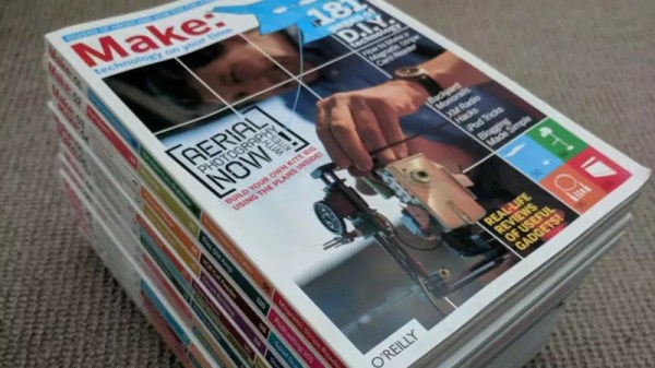
Between the first issue of Make magazine in 2005 and the inaugural Maker Faire a year later, Maker Media deftly cultured the public face of the “maker movement” for over a decade. They didn’t create maker culture, but there’s no question that they put a spotlight on this part of the larger tech world. In fact, it’s not an exaggeration to say that the shuttering of Maker Media could have far reaching consequences that we won’t fully understand for years.
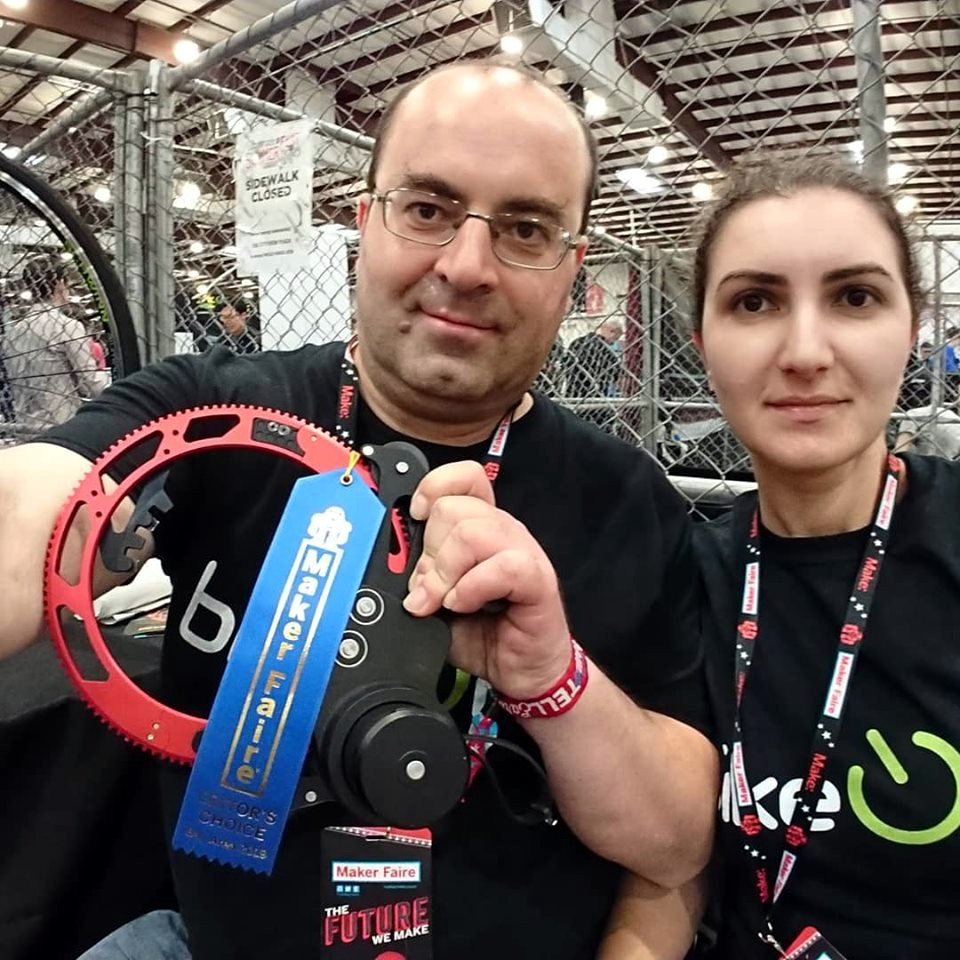
![]() While this news will surely come as a crushing blow to many in the community, Maker Media founder and CEO Dale Dougherty says they’re still trying to put the pieces together. “I started the magazine and I’m committed to keeping that going because it means something to a lot of people and means something to me.” At this point, Dale tells us that Maker Media is officially in a state of insolvency. This is an important distinction, and means that the company still has a chance to right the ship before being forced to declare outright bankruptcy.
While this news will surely come as a crushing blow to many in the community, Maker Media founder and CEO Dale Dougherty says they’re still trying to put the pieces together. “I started the magazine and I’m committed to keeping that going because it means something to a lot of people and means something to me.” At this point, Dale tells us that Maker Media is officially in a state of insolvency. This is an important distinction, and means that the company still has a chance to right the ship before being forced to declare outright bankruptcy.
In layman’s terms, the fate of Make magazine and Maker Faire is currently uncertain. The intent is to restructure the organization and rehire enough people to keep the brand alive, but it may take rethinking their business model entirely. While they aren’t looking to crowdsource the resurrection of Make, Dale said he believes the answer may ultimately come from the community’s willingness to financially support them, “my question is can we perhaps rely on the community to offer support for what we’re doing in ways we have not asked for in the past.” Ideas currently being discussed include the sort of annual membership and pledge drives used by public broadcasting.
It’s impossible to overstate the positive influence that Make has had on the public’s perception of DIY. It put on a global pedestal the sort of projects which otherwise might have never been seen outside the basement workshops or garages they were constructed in. Through their events and outreach programs, Make showed an entire generation of young people that building something just for the joy of building it was something to be proud of. Make proved that nerds could be cool in a way that had never been done before, and worryingly, may never be done again. Let’s take a look at that legacy.